

Rebuilding an E-Skateboard (esk8)
I have an old Evolve Carbon GT skateboard donated to me by my brother – a project he hadn’t got around to working on. Being a skater in my youth I decided I would love to give it a crack! Step one was cleaning it, then completing it with the parts he had already arranged for it which involved completing assembling a battery pack (original batteries had been removed), wiring up the Battery Management System (BMS) and charging and testing.
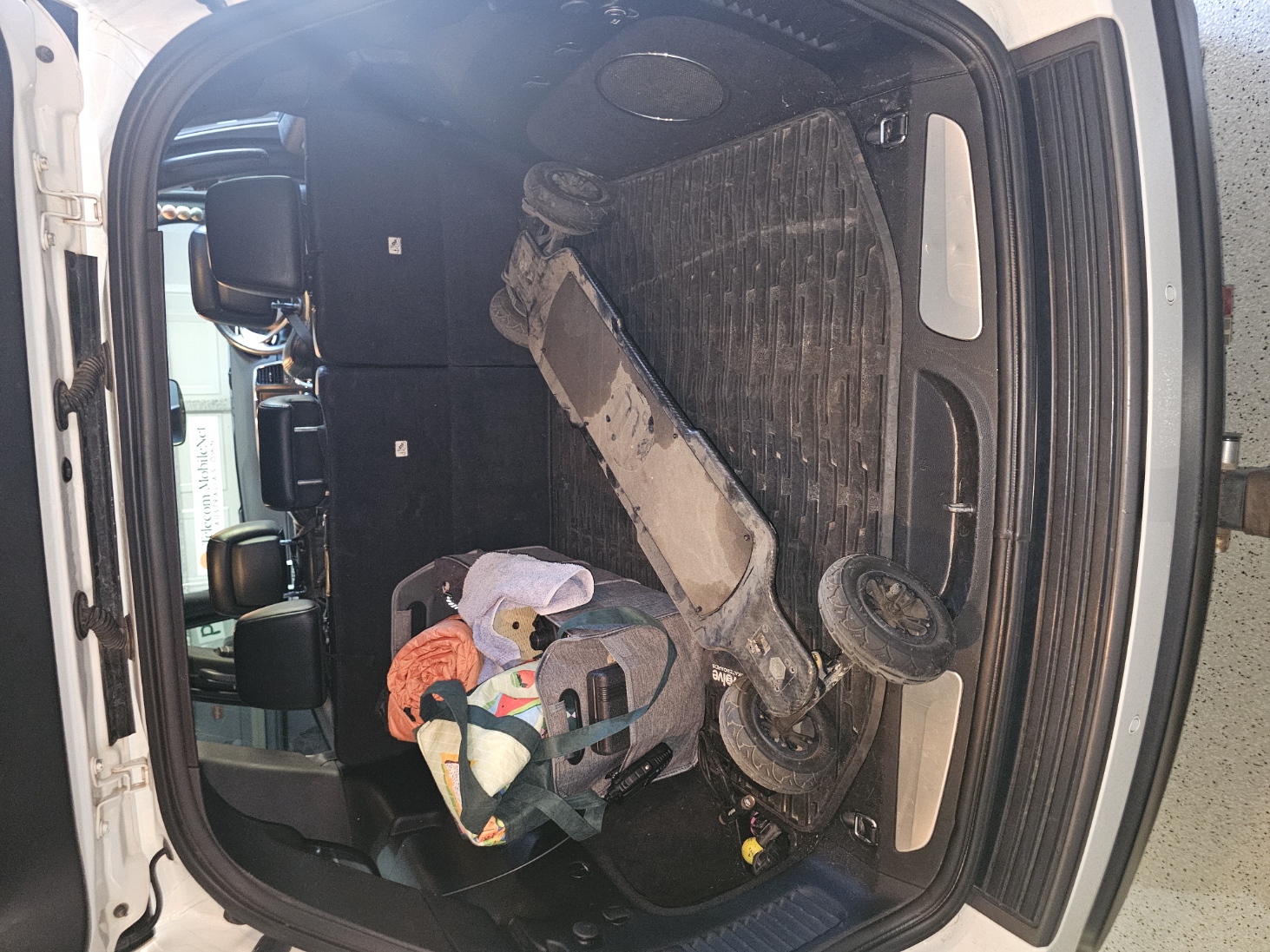
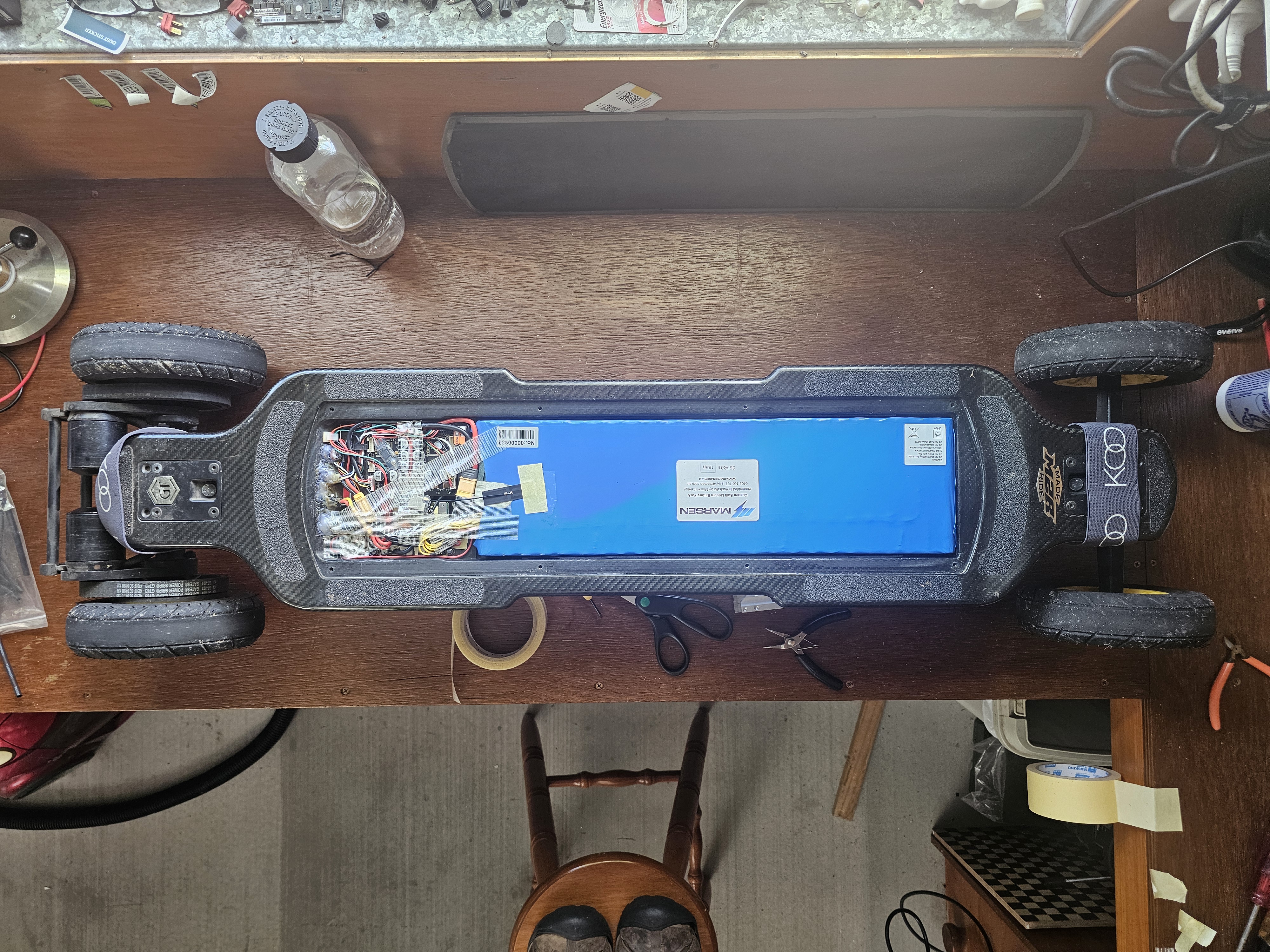
Cleaning was fun, a year or so sitting in a workshop, paint overspray, metal grindings embedded into the gel coat, oil film over a lot of it (the dark patch on the deck in the above picture is oil), tyres out of round, bearings making odd noises etc. A good day cleaning, a light wet sand with 2000 grit, polishing, adding some extra grip tape on the edges, new bearings, new tyres etc, the final result was pretty impressive if I do say so myself. Quickly jumping ahead for a moment, this was the end result (deck lid is just sitting in place, not screwed down):
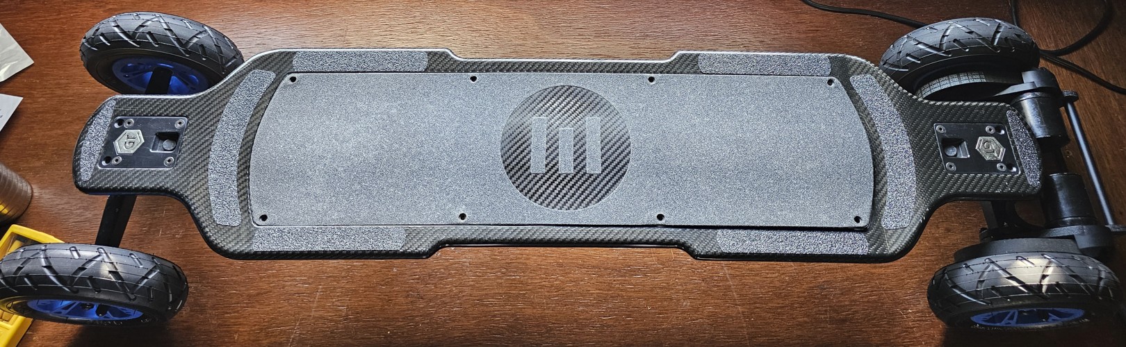
Took a few attempts to get it working, something was stopping it from allowing itself to run (it turned on, but wouldn’t go). After a while I had re-calibrated the Evolve R2 remote, that made it work intermittently, then re-soldered all wiring connections on the circuit boards, removed some minor corrosion, and finally discovered plenty of the old glue holding wiring and capacitors stationary. That glue goes brown and slightly conductive as it bakes with heat. So that was all carefully removed which also revealed the battery temperature sensor wires were actually corroded through and only touching sometimes because the glue was holding them in place (battery temp sensor failure tells the ESC its not suitable to go). Also ordered a new (larger) battery for the remote as it wasn’t holding charge for too long – ordered a 102050 1000ma battery (10mm x 20mm x 50mm) – wiring was reversed so had to swap the pins in the plug.
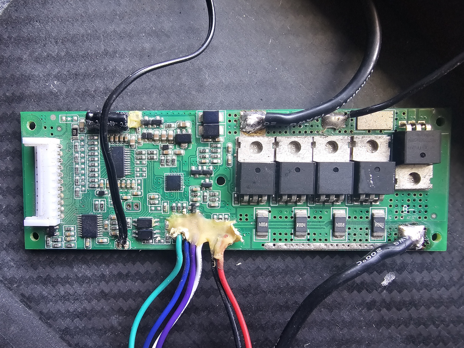
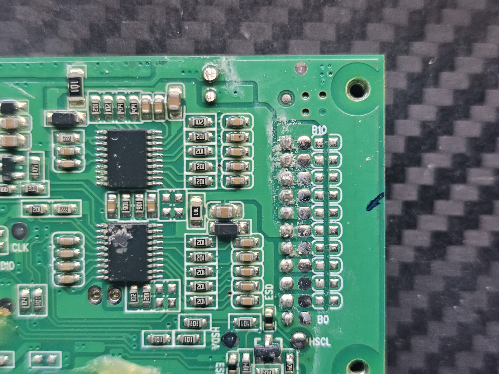
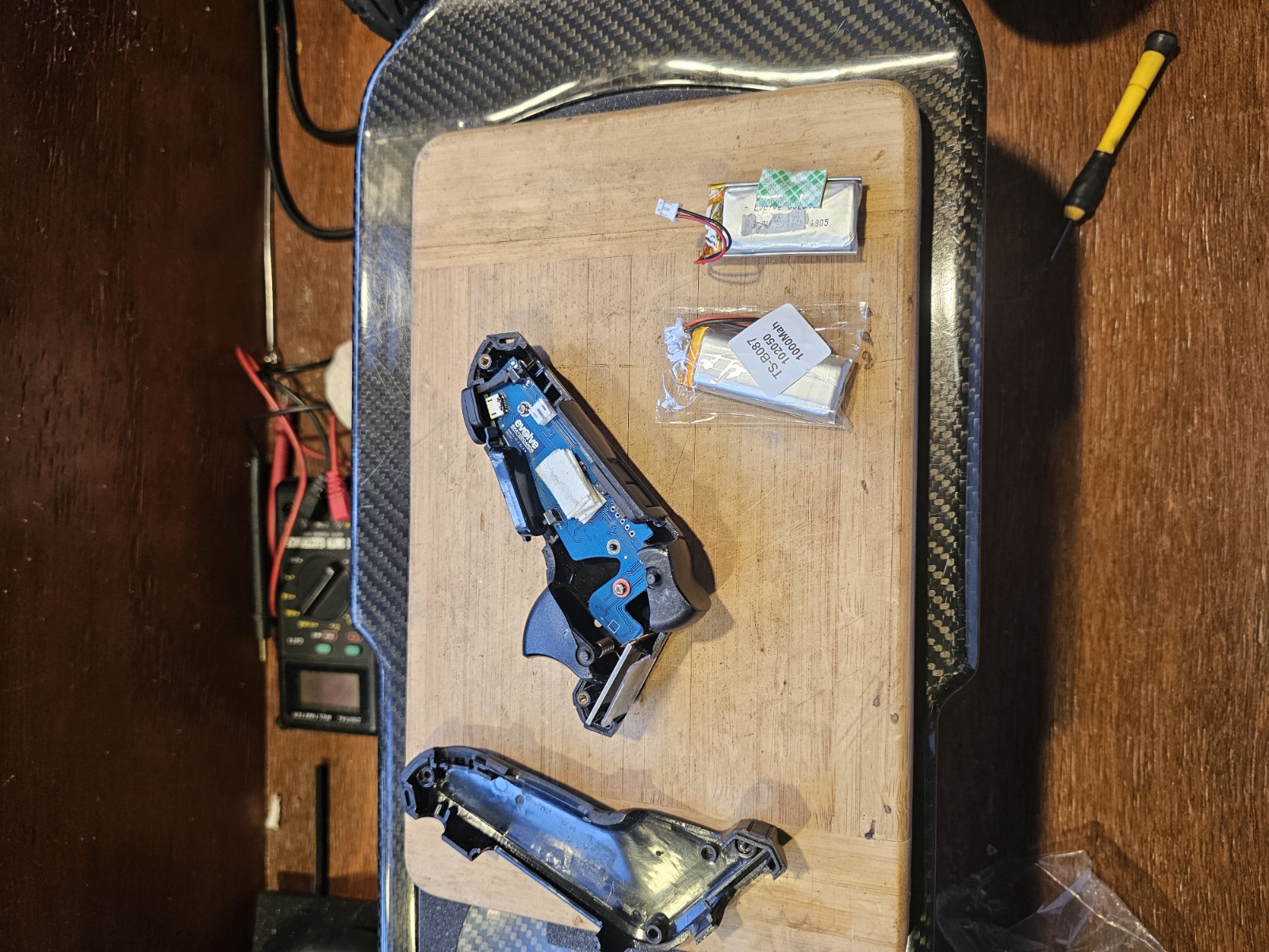
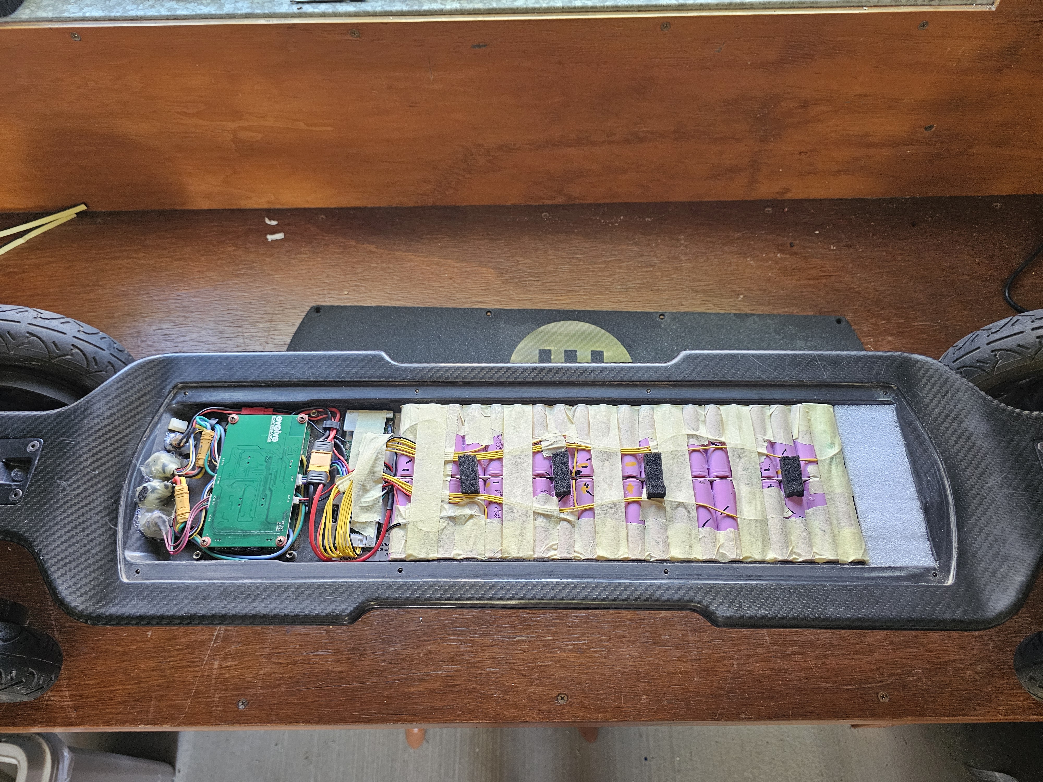
Once all that sorted it was more reliable and I was able to ride around at a max 10 to 12kmh and in Eco mode only, any more power than that and the battery level dropped so far it shut down and rebooted. But I was able to get a good 10 min running around slowly several times and that was enough to convince me to get it running properly.
Only thing not working at this stage was the battery, so I ordered a 10s5p pack from Marsen in Western Australia. Not cheap, but 50% more capacity and 3 times the maximum current rating meaning the voltage would not drop much under full power. Battery arrived, installed, wow… 37kmh, 25km range and a bucket load of fun! Of course, I had bought knee and elbow pads, wrist guards and a decent helmet whilst waiting for the battery to arrive and have not ridden it without them yet.
Next the tyres were a bit ‘off’ – it had been sitting for quite a while and looks like the tyres were resting on an oily surface. The oil had absorbed into the tyre rubber and the inner tubes, creating a golf ball diameter lump about 5mm high on all 4 tyres. So new tyres and tubes ordered from Evolve – damn, $95 for 4 tyres and $20 each for tubes! Oh well, doesn’t work without them. While there decided should also replace the wheel bearings since who knows what condition they are in. They all arrived before the battery, so got them installed, however they had new blue rims on special for $5 each and that bumped the over all price high enough for free freight 🙂 (I have since ordered tyres from AliExpress, same size, $16 each including tubes / $64 total, delivered… 1150km later they are still going, though very low on tread now)
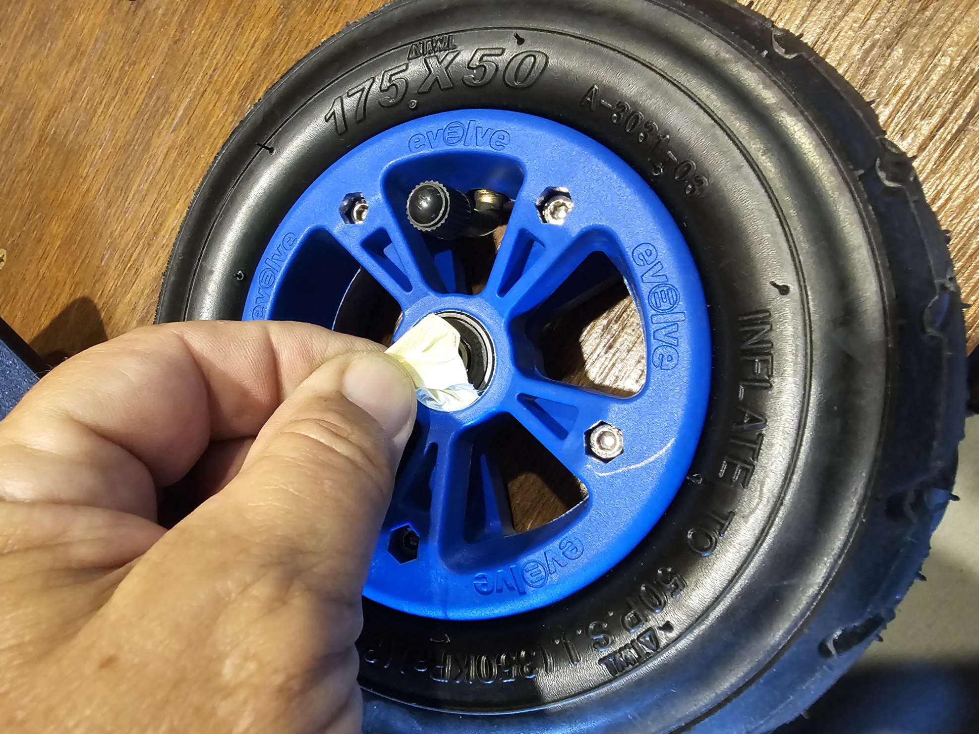
However the mould of the new blue rims was a bit off and the bearings were not a firm press in fit like they should be. This allowed the wheels to wobble significantly side to side when changing directions, making the tyre hit the cover over the motor pinion! A lot of thinking and experimenting, first I wrapped the bearing in masking tape, inserted them, trimmed off the excess and this worked perfect, though after a few 100km the tape slowly worked its way out. Second option was to cut a small square from thin cloth (think handkerchief thin – I used a Chux Wipe), cut a hole for the axle, place it on the wheel and push the bearing in place with the cloth behind. Once in place, trim off the excess cloth and apply a few drips if super glue around the outer bearing edge that soaks into the cloth, seems to work great (edit – 1,000km later still not moved)
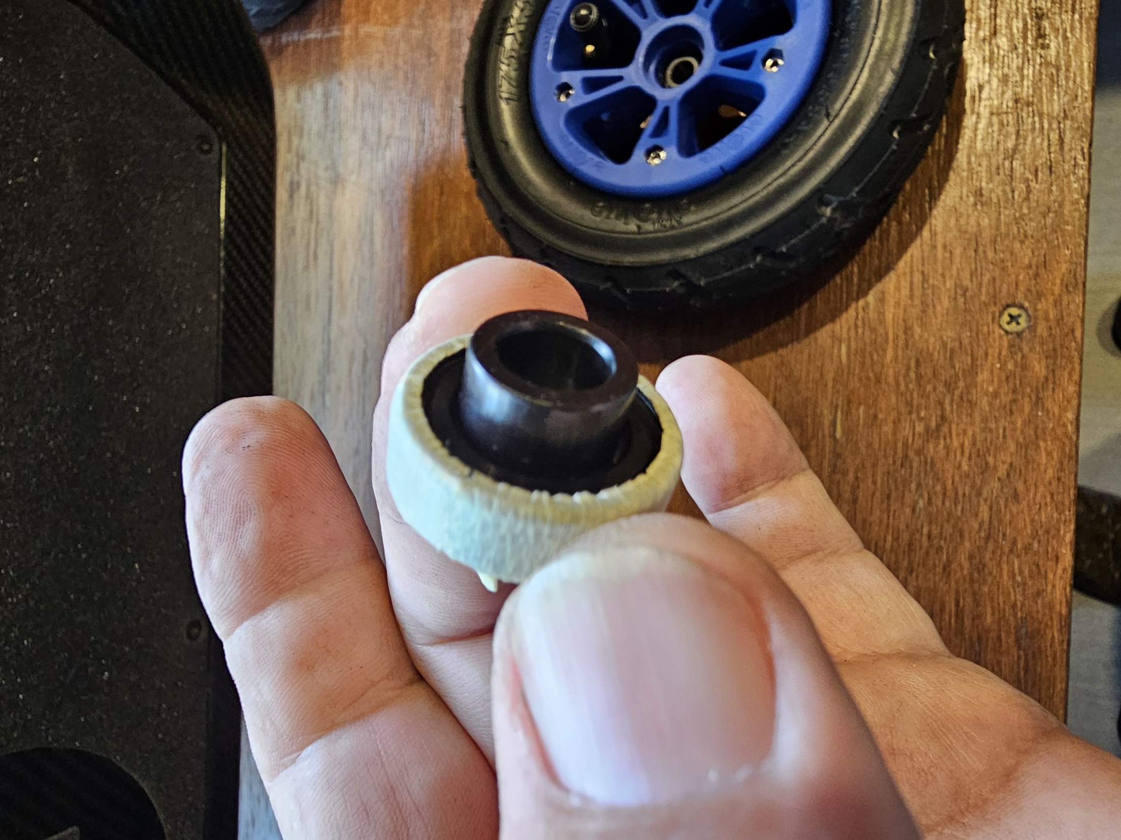
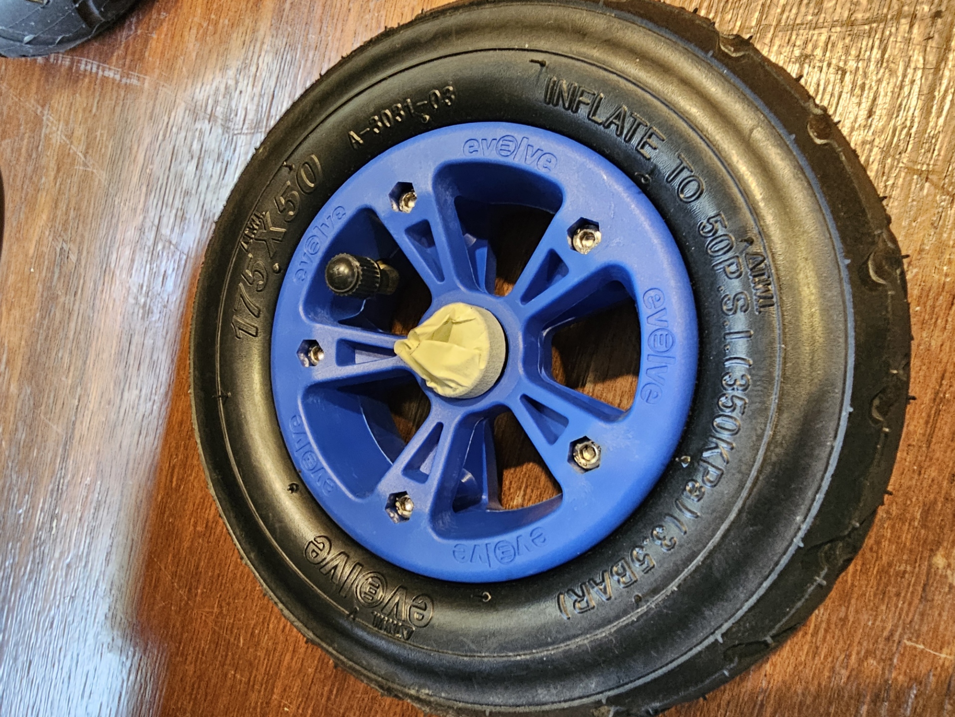
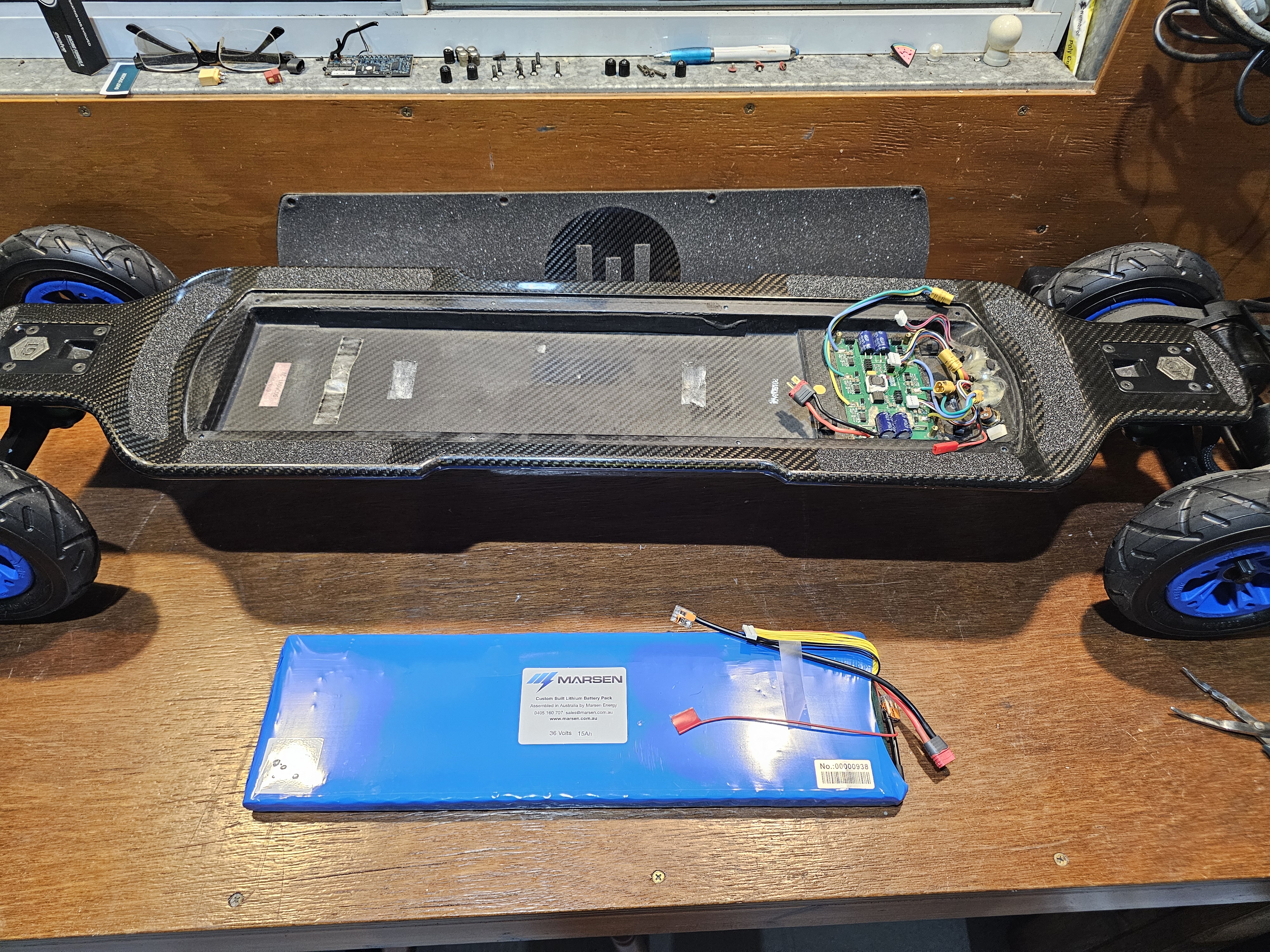
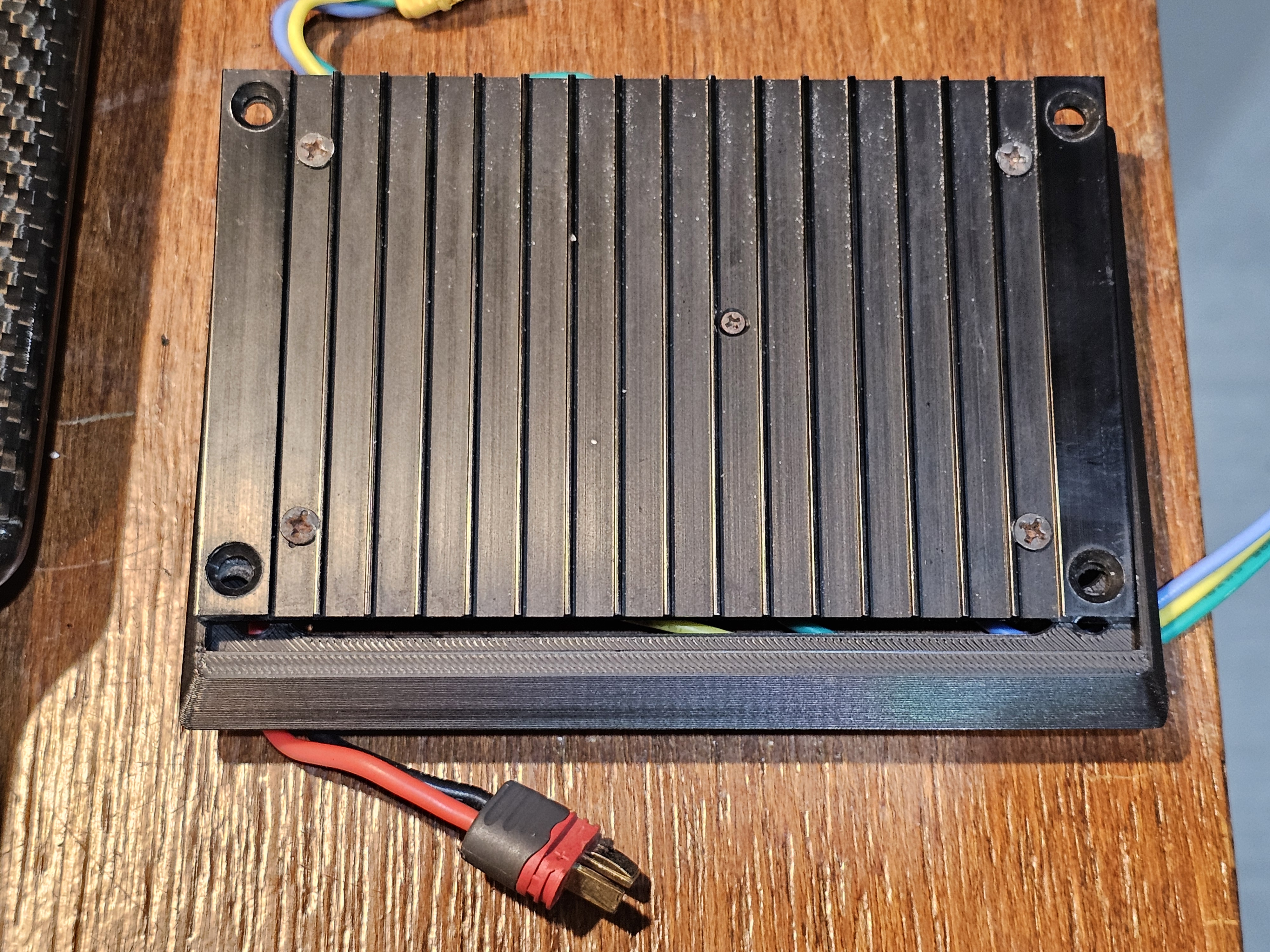
New battery finally arrived from Marsen (road freight only being Lithium, coming from the other side of the country), with a spacer to drop the electronics down. Why? The original battery is about 50mmm shorter than the area the battery sits, allowing space for the BMS to be attached to the battery and sits in that section with it (in fact the original battery it was part of the pack). The new 50% larger capacity battery is 5 cells (90mm) longer leaving no room for the BMS, so we have to lower the heat sink that the Electronic Speed Controller (ESC) mounts to by enough for the BMS to sit on top of it. Not complicated, just fiddly. Eventually I had everything sitting in place nicely and the spacer sealed in place with silicone to prevent (or reduce) water ingress.
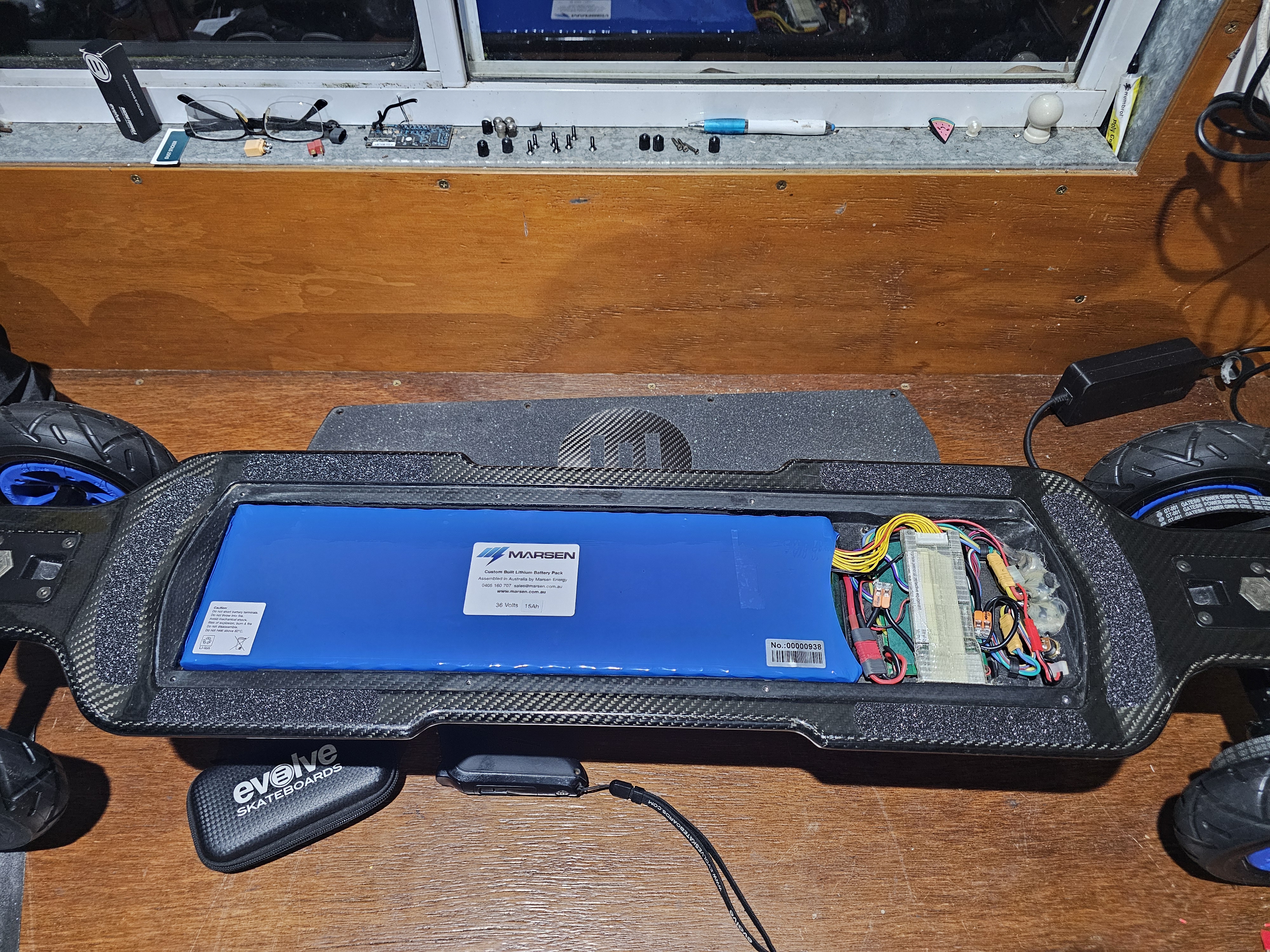
Really happy with how it all cleaned up and performance was excellent. A few minor glitches with intermittent operations, worked out to recalibrate the remote triggers, holding them in slightly when setting the minimum point. This gave a little leeway tolerance as the plastics may have been worn slightly and it wasn’t always detecting the brake or accelerator position as 0 when turned on and then wouldn’t allow you to move. (Safety feedback)
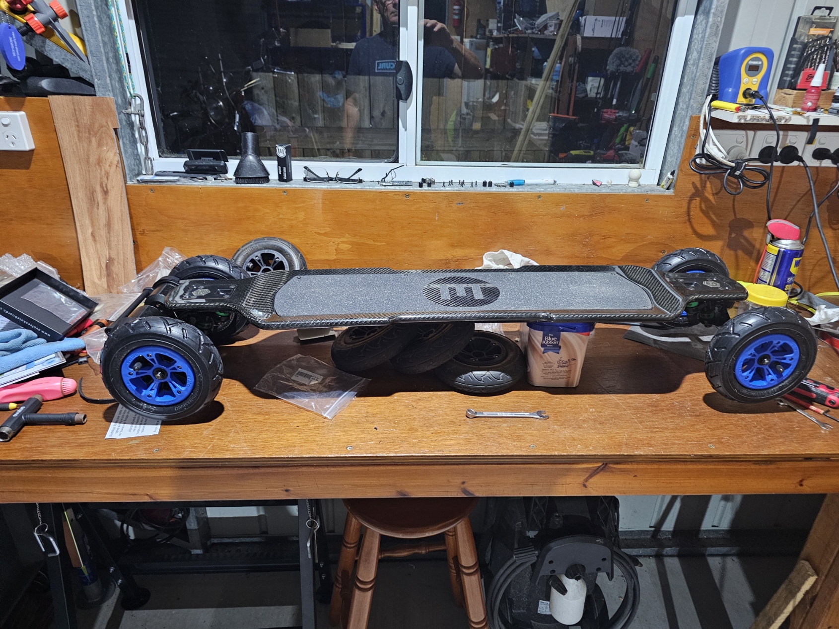
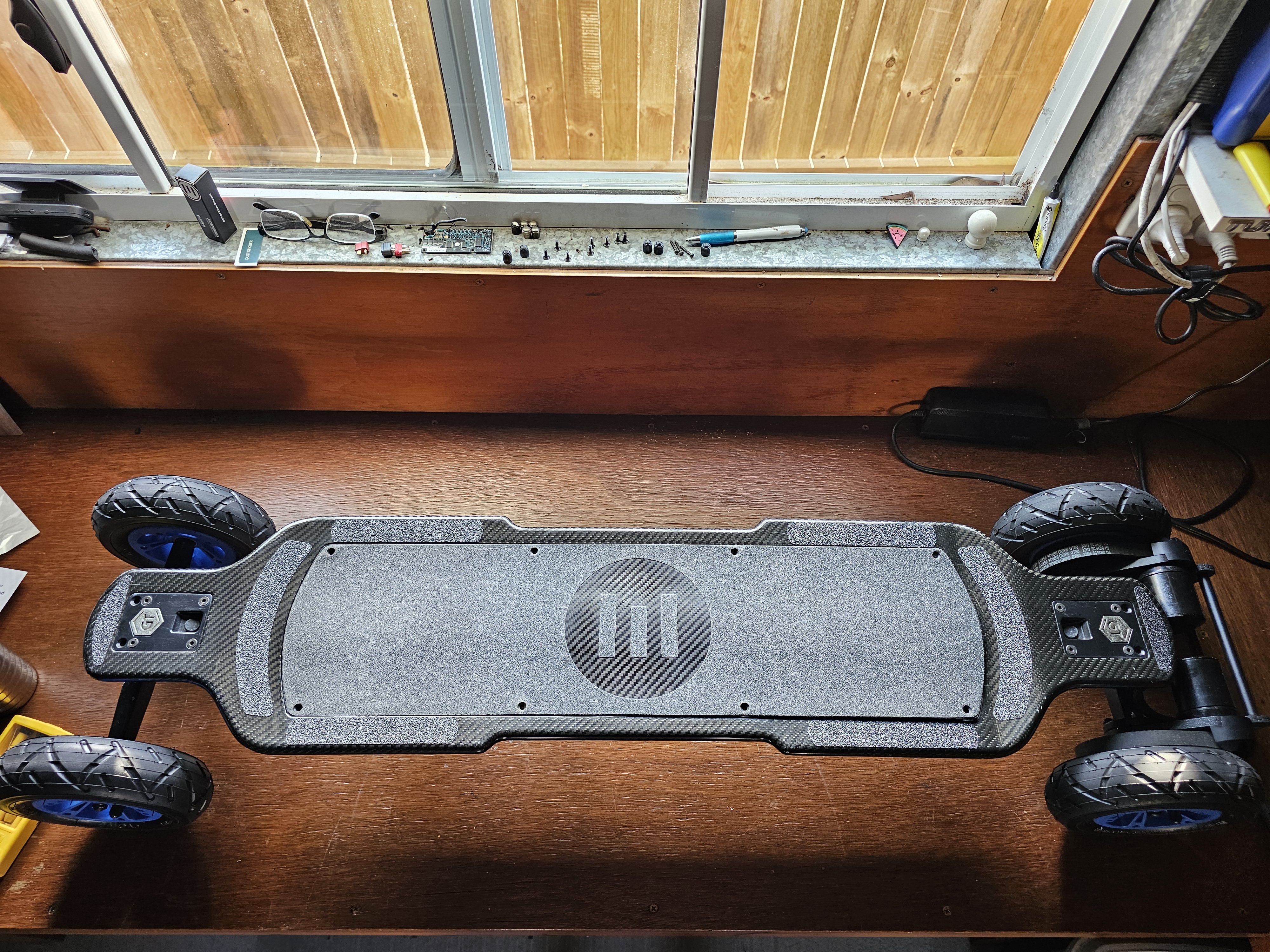
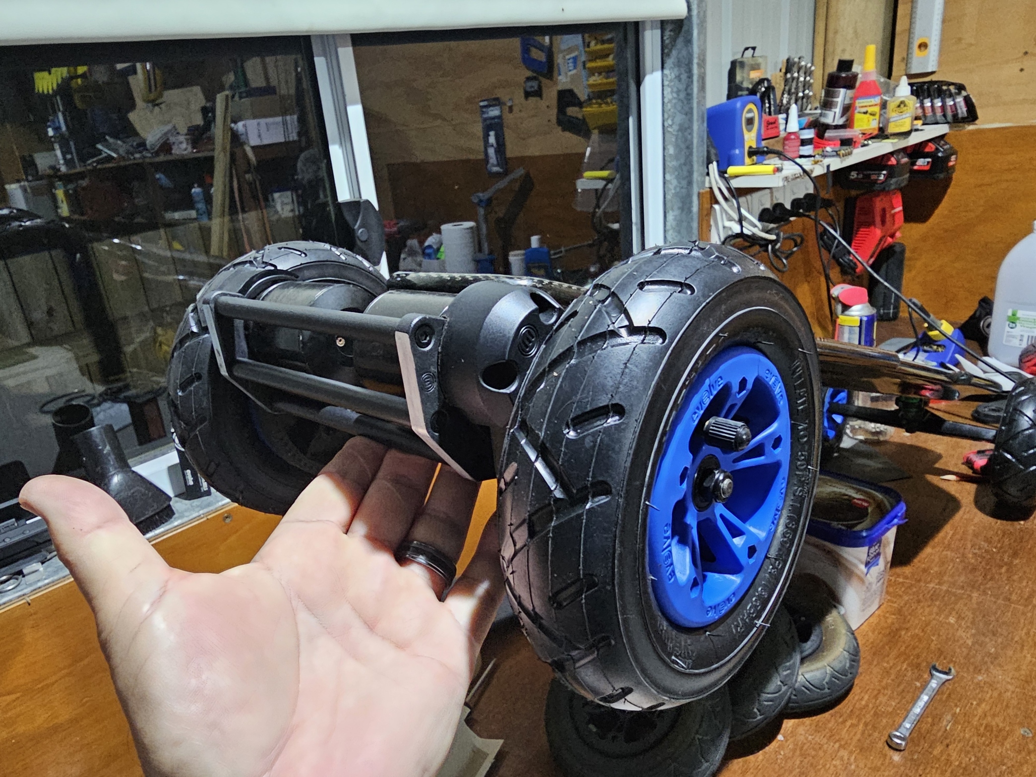
This is how I rode it for the next 3 months and 1500km, very happy, a few times a week at 20 to 25km each ride. Happy place!! Evolve was also good about the wheels issue and sent me a set of yellow hubs free due to the moulding issue (they were a fraction better, but still needed a cloth in behind the bearing to stop the casing spinning freely inside the hub).
So… 3 months and 1500km later, we had a few long days of rain and I was getting itchy feet from not riding. Rain finally stopped one morning, went out about lunch time and noticed there was still a lot of wet ground so had to slow right down to stop the water spraying up. Thought it was too wet, so rode back home averaging about 5kmh the whole way to try and keep everything dry. Got home, stood the board up, electronics at the highest point just case any liquid did get in and didn’t think about it again. Next day went to go for a ride and totally dead, would not turn on at all. DAMN….
Time for some old school fault finding (that’s my background). After a lot of stuffing around, identified the BMS was not turning on which cuts the negative battery connection to the ESC, causing it to not turn on either. The switch was operating correctly so the BMS should have turned on, in turn providing power to the ESC.. Shorting the negative in/out wires on the BMS to effectively bypass the BMS power switching, and the ESC fires up fine and all seemed to work. However the Evolve BMS and ESC also talk to each other over a proprietary serial data link… This is so the BMS can tell the ESC if the battery is not in a fit condition to work at full power (low cell, over heat etc) and the ESC then locks back to Slow mode, approximately 5kmh. Lots of searching, googling etc, turns out the best option is start replacing parts. Of course the BMS is proprietary, so either buy the original or nothing. None available, couldn’t find any second hand. Next option is if you replace the BMS, you also have to replace the ESC and then the remote as it is proprietary to the ESC…. FFS…
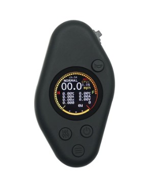
Oh well, I am hooked now and close to $1000 Aus invested, so a lot more research (googling) trying to find what would work and would physically fit and the results were not much due to the very small space. After a recommendation from another C GT rider who went through the similar issue, I ordered a FlipSky Dual FSESC4.20 Plus (Based on VESC) with Anodised Aluminium Heatsink and Anti Spark switch, Bluetooth programming adaptor, a JBD SP14S004 50/150amp BMS with Bluetooth, and a FlipSky VX4Pro controller. About $340 Aus delivered.
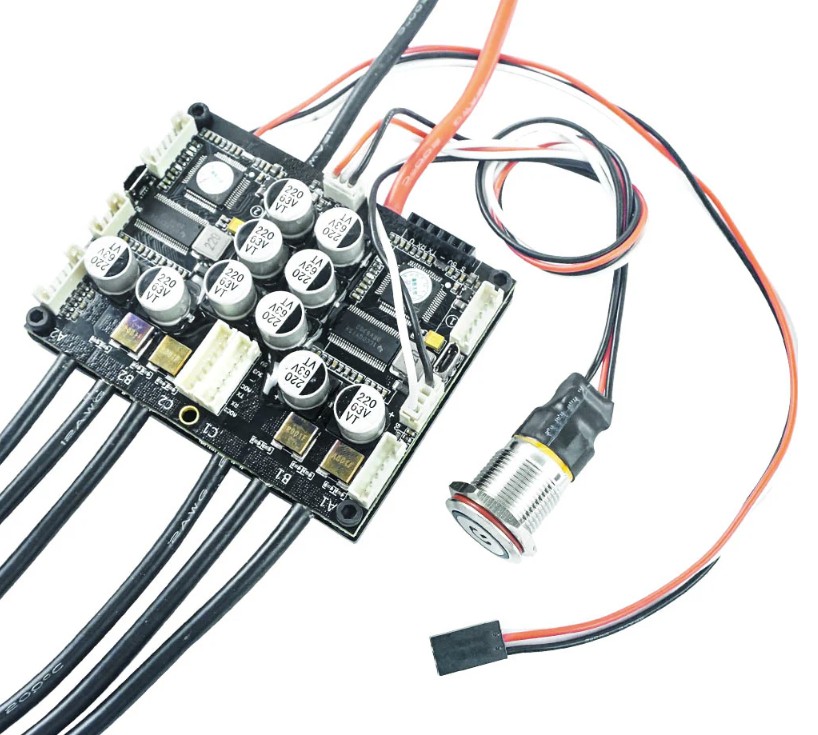
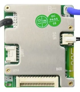
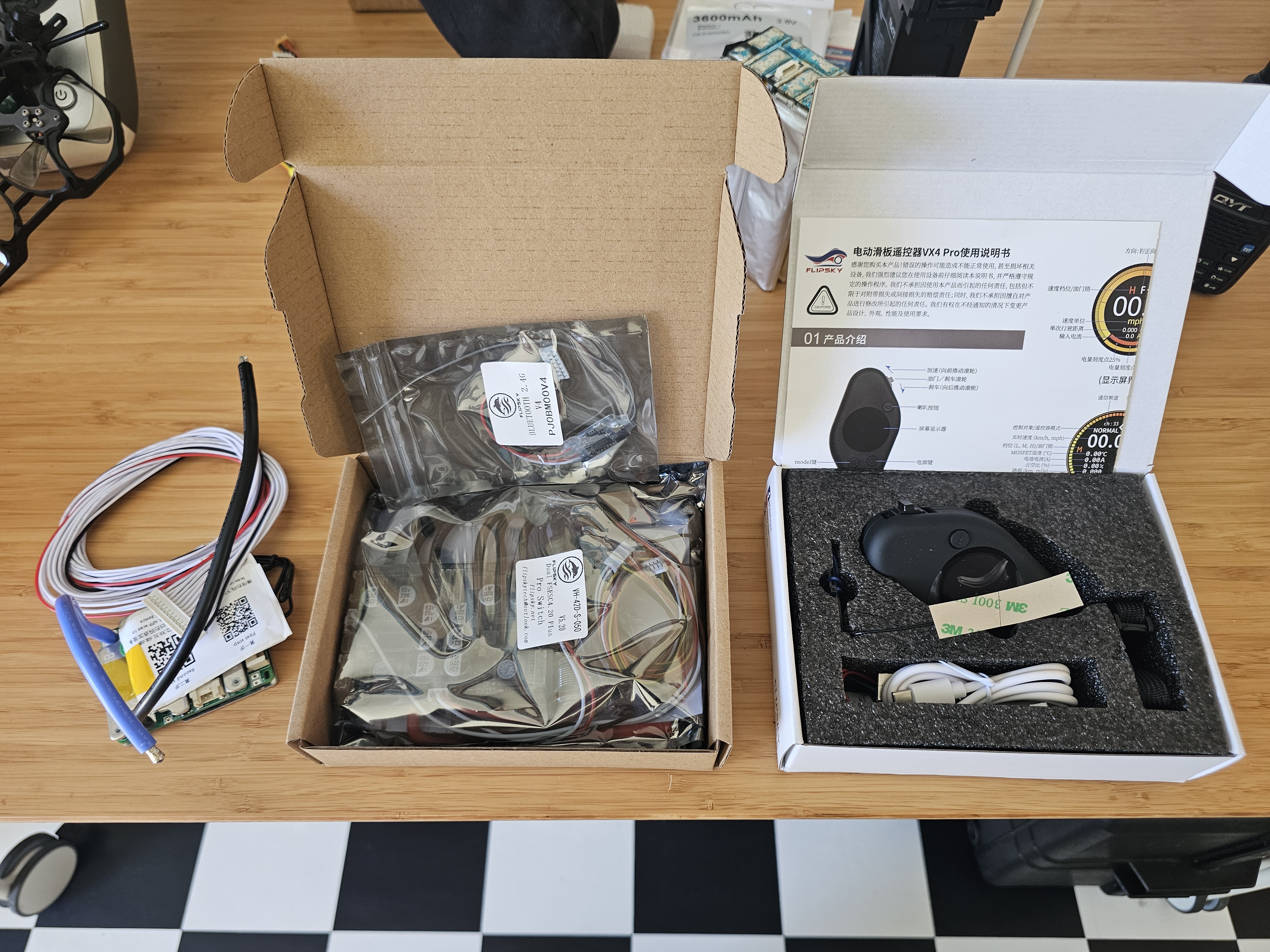
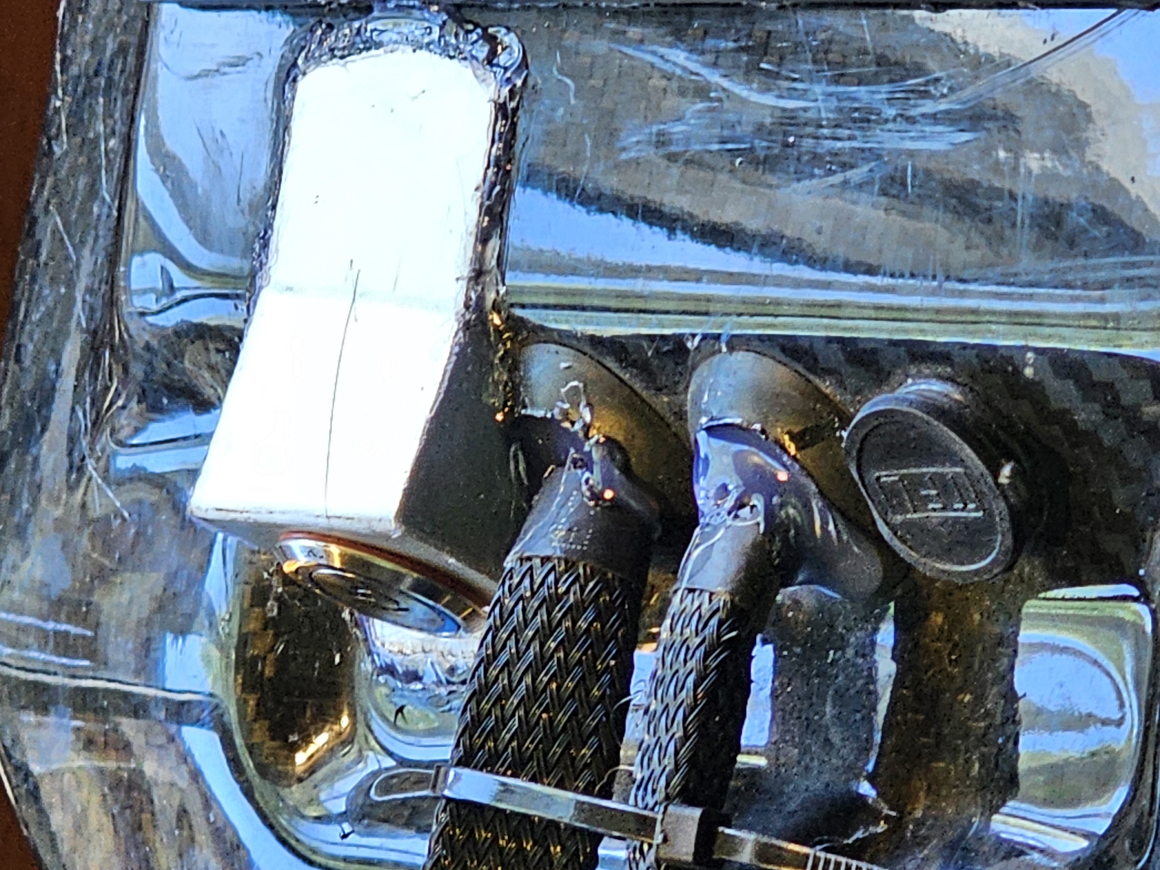
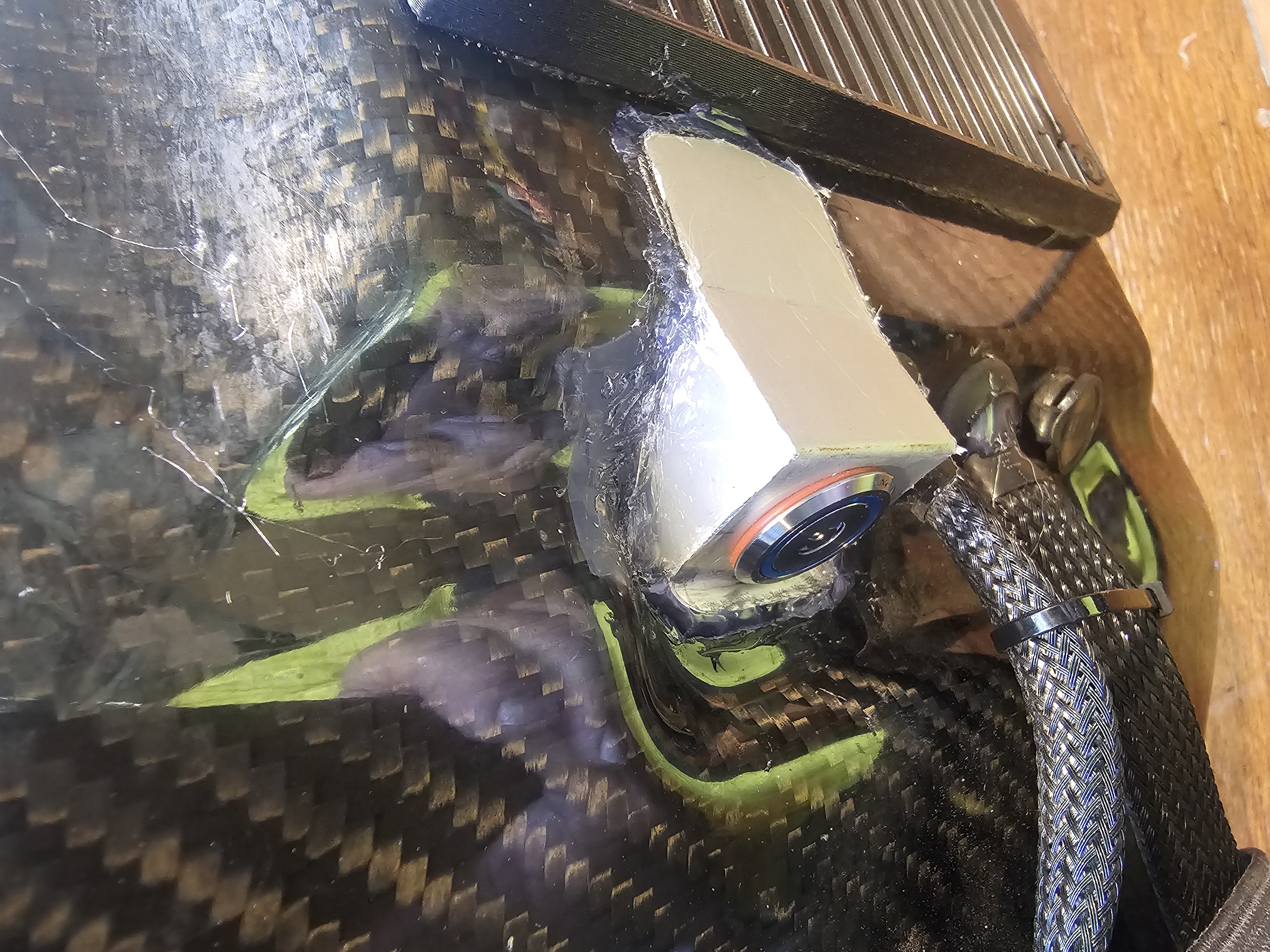
The FSESC is bigger and thicker than the original, so had to work out how to fit (more on that later). The power switch is also a lot longer and bigger overall (includes AntiSpark so when connecting the battery lead no big electronics killing sparks). I enlarged the hole for the power switch to fit, but when inserted the back end was about 15mm higher than the deck! So I bent up some 1mm Aluminium sheet scrap to make a bracket to mount the switch almost horizontal and to and hold the switch around 15mm out from the body, mounted the switch to the bracket then glued the bracket in place with a silicone glue, then filled the sides and the gaps with hot melt glue… You will notice I also filled any gaps in the cable grommets with glue as well to try and reduce any more water ingress…
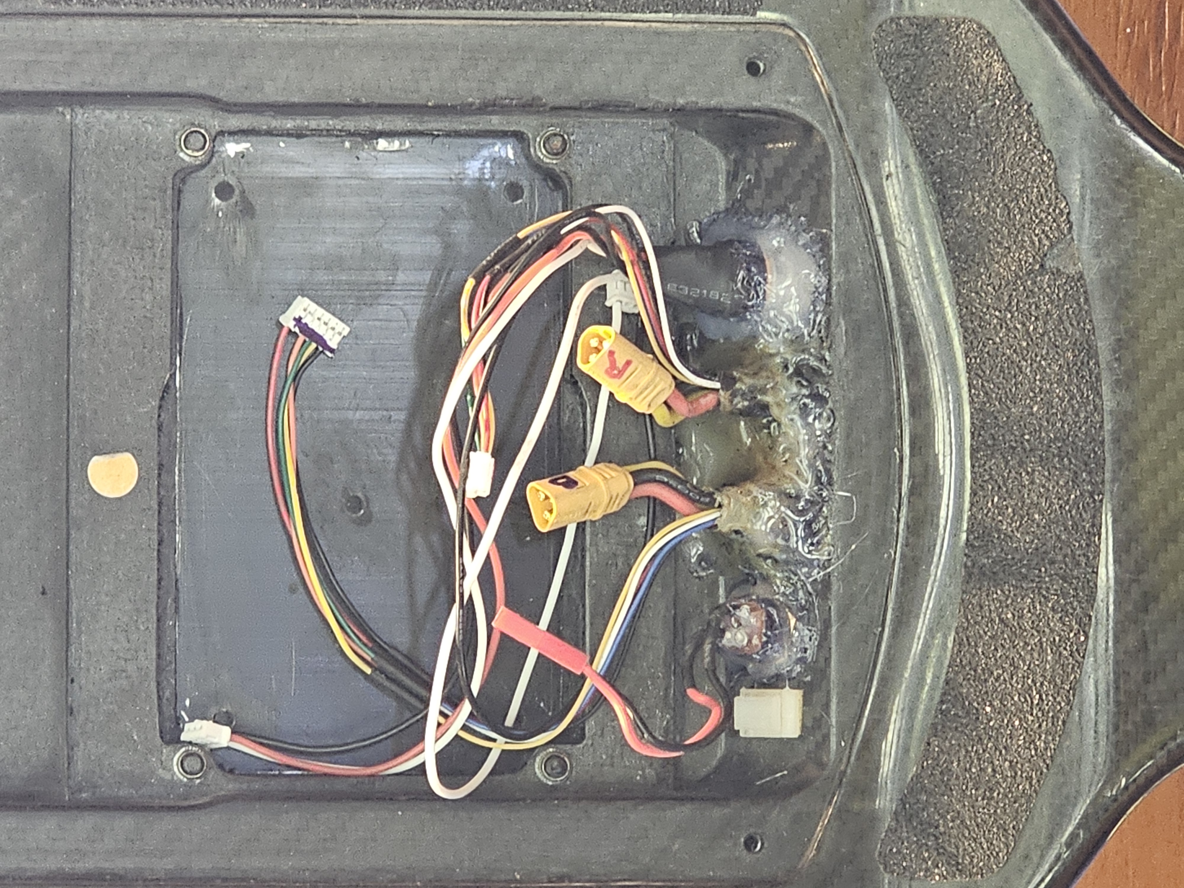
Next was trying to get everything to fit.. Removed all original electronics and cleaned up any grease and sticky stuff to start from fresh. As you can see in the first pic below, the ESC is too wide to fit in the existing cutout, so some mods were in need.. I couldn’t turn it 90° as then there was not enough room for the BMS too. The Evolve heat sink has been removed here, but the spacer is still there as its glued in place from previous to reduce water. Marked out and got the Dremel and started at it. Because I would be going to the full width of the heat sink, I decided I would leave a small lip at the bottom to assist with sticking the Heatsink in place with silicone for waterproofing. I reinstalled the heatsink and used a 0.5mm piece of scrap aluminium sitting on the heatsink and butted it ap against the edge, then used a 10mm diameter drum sander in the Dremel to carve out the size needed. I also trimmed out the ends to account for the ESC power cables and for the BMS to slide across as far as possible. I did trim even more later to get a few more millimetres between the two boards.
I have also replaced the Motor wiring from the original 12g shown below to 14g to match the existing motor wiring and reduce cable thickness, and I cut/resoldered the 12g power leads due to them not bending. All original leads had been allowed to let the solder wick up the cables at least 10mm, making them rigid straight out from the board. They are now tucked in neatly against the board.

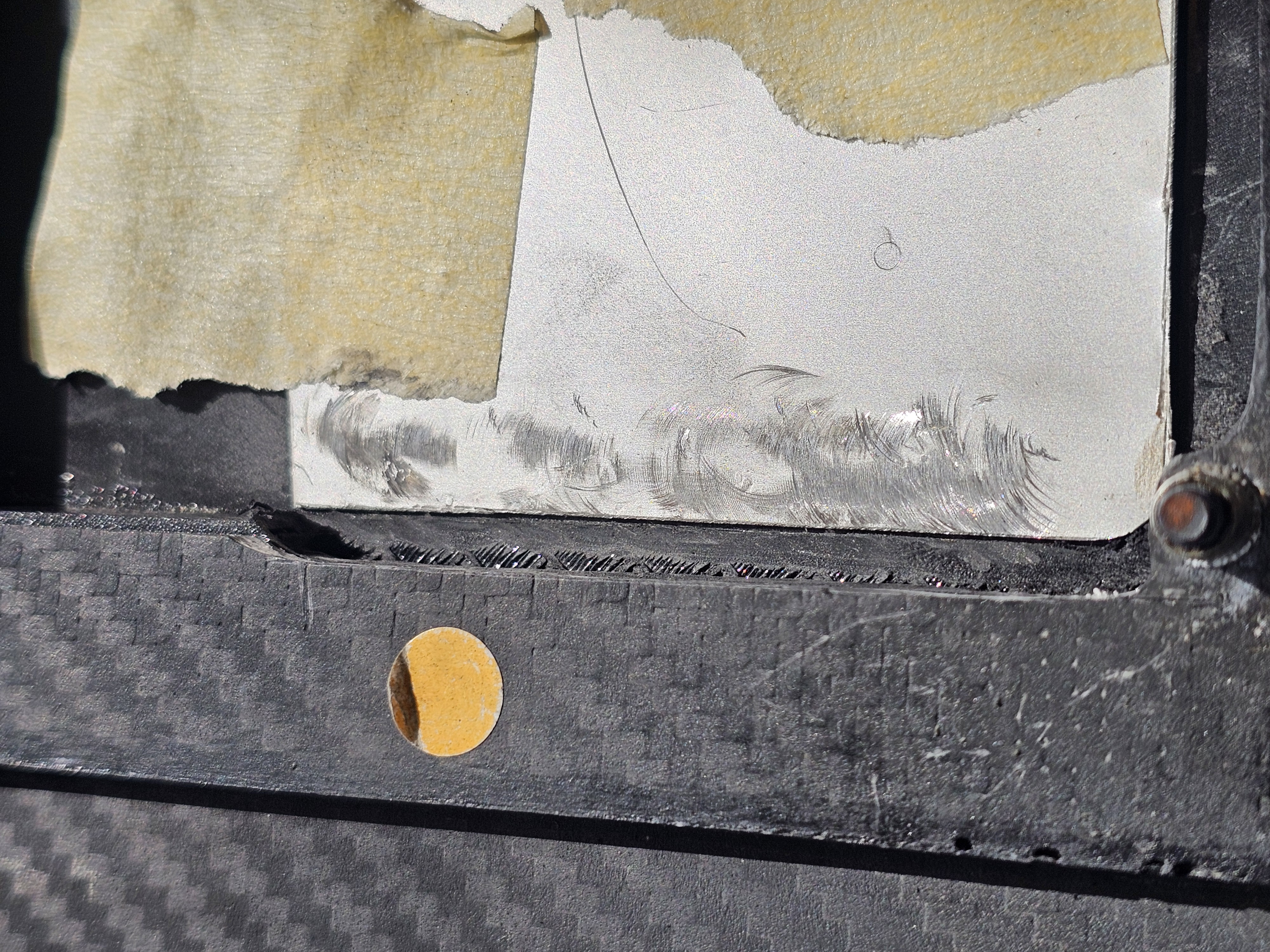
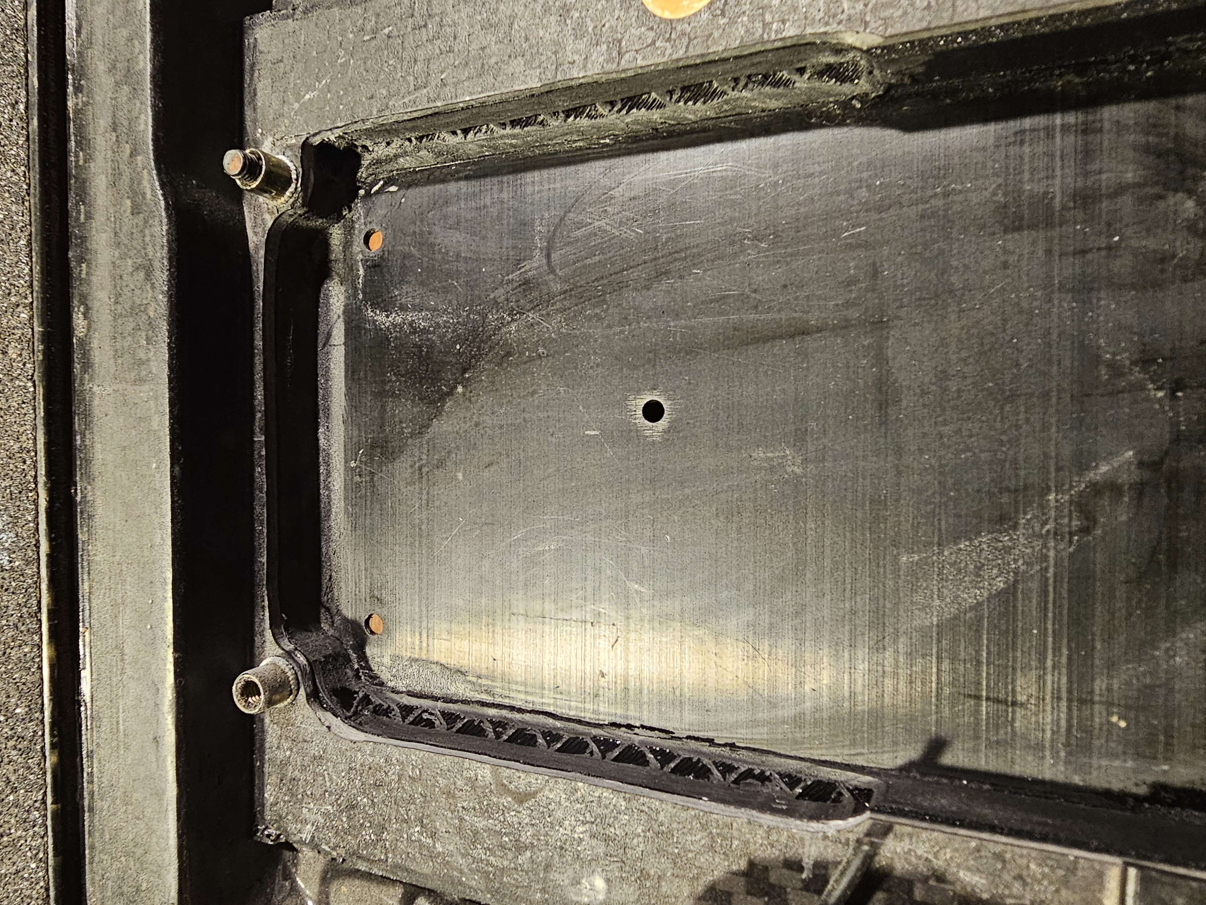
Whilst I had the Heatsink removed form the ESC, I also looked into the receiver cabling connections. After a lot of googling, I worked out the black tall connector was the UART and correct connection point, not either of the two other COMMS ports. No compatible plugs were provided, however I did have some pin style plugs I could use from my RC gear, but anything plugged into this would end up way higher than the deck. So I cut the plug off one of the the 2 receiver cables provided and soldered to the bottom of the board directly, hot glueing the cables where soldered and to the original socket for stability. You can see in the middle pic below the power wires bending a good 10mm away from the board as mentioned above! The receiver also has a blue wire soldered to it, that needs to be connected to the Battery positive which you can see I have connected in the screw in wire joiner in the first of the final assembly photos a few blocks down. However… when using UART you dont need that wire as the battery voltage is fed back through the telelmetry, you only need it if connected voa PPM. So after the last photos it was snipepd off.
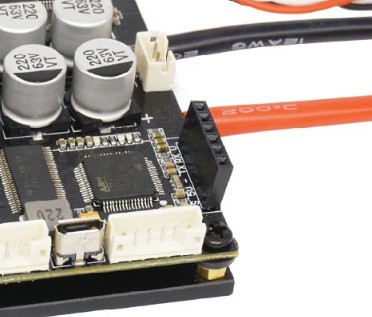
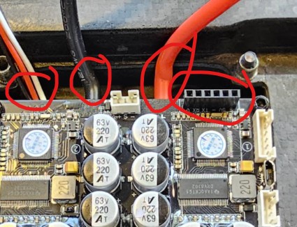
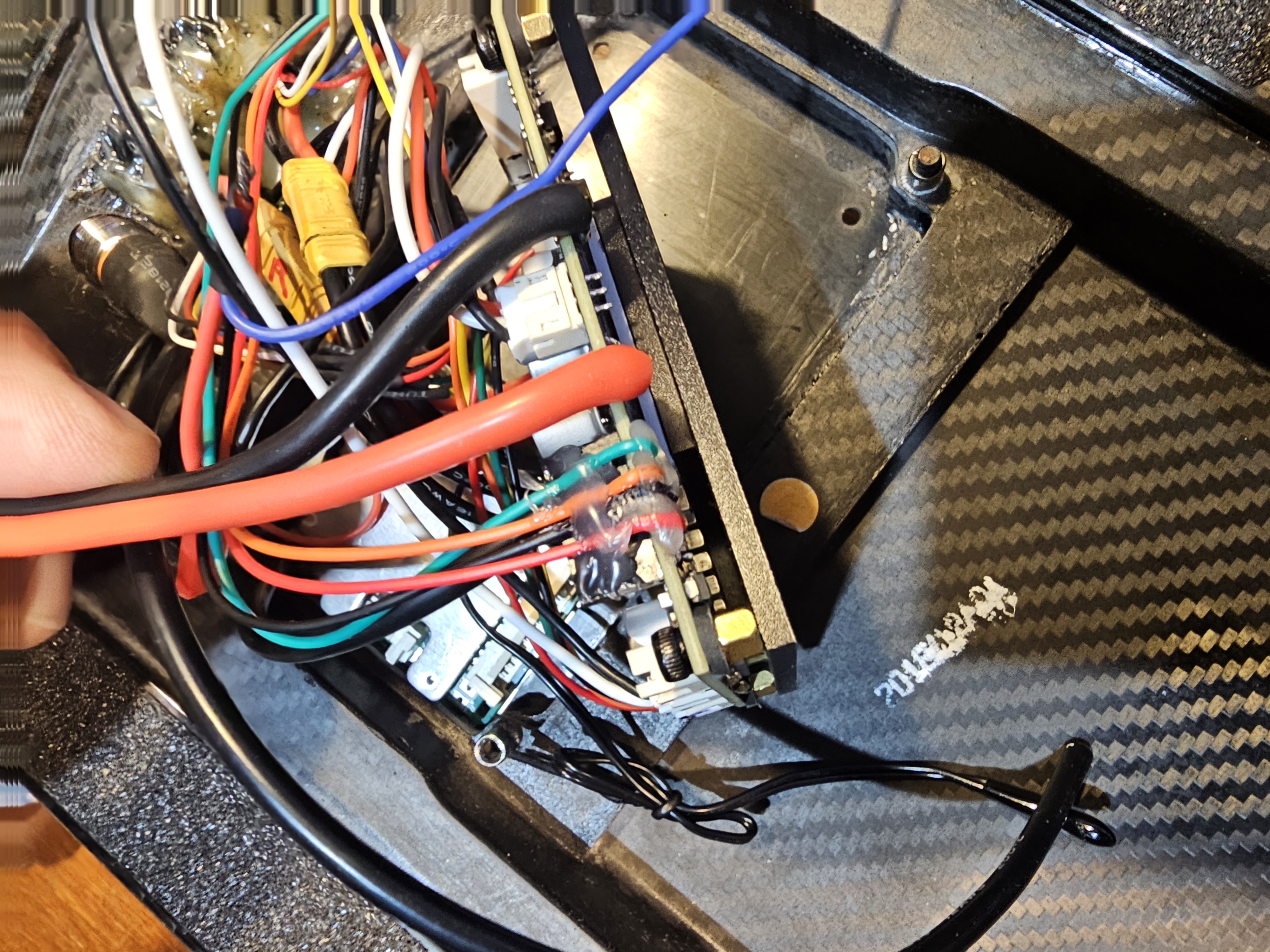
The Motor wiring – I reused the motor plugs from the original ESC, soldering them on to the new 14g wires. Orientation is not important, the motor direction is set by the wire order and that can also be changed in programming easily. Motor sensors – Evolve motors use 5 wires – black and red for negative and positive, then yellow, blue and white for the Hall Sensors – no temperature sensor. The leads than come with the FSESC are 6 wire, the 5 mentioned plus a white temperature sensor wire. The white temp sensor is not needed for these motors, so simply remove that wire/pin completely then join the red and black to red and black, then the three colours together and order is not important.
BMS Install. I bought a JBD BMS as mentioned above, good price, features 50amp continuous and 150amp surge, plus balancing for all cells during charge and/or discharging. Balance lead connects from the negative, but as the BMS allows for 7 to 14 cells, the socket is designed with 15 pins. Pin 1 to Negative of cell 1, pin 2 to positive of cell 1, pin 3 to positive of cell 2, pin 4 to positive of cell 3 etc. Once you have reached the number of cells in use (10 for me), all remaining pins connect to that last cells positive. (test ride today showed an absolute max 25amps from the battery, so well within normal specs)
B- is to the battery negative, C- is to the ESC and charger (so discharge and charge runs through the BMS control)
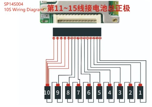
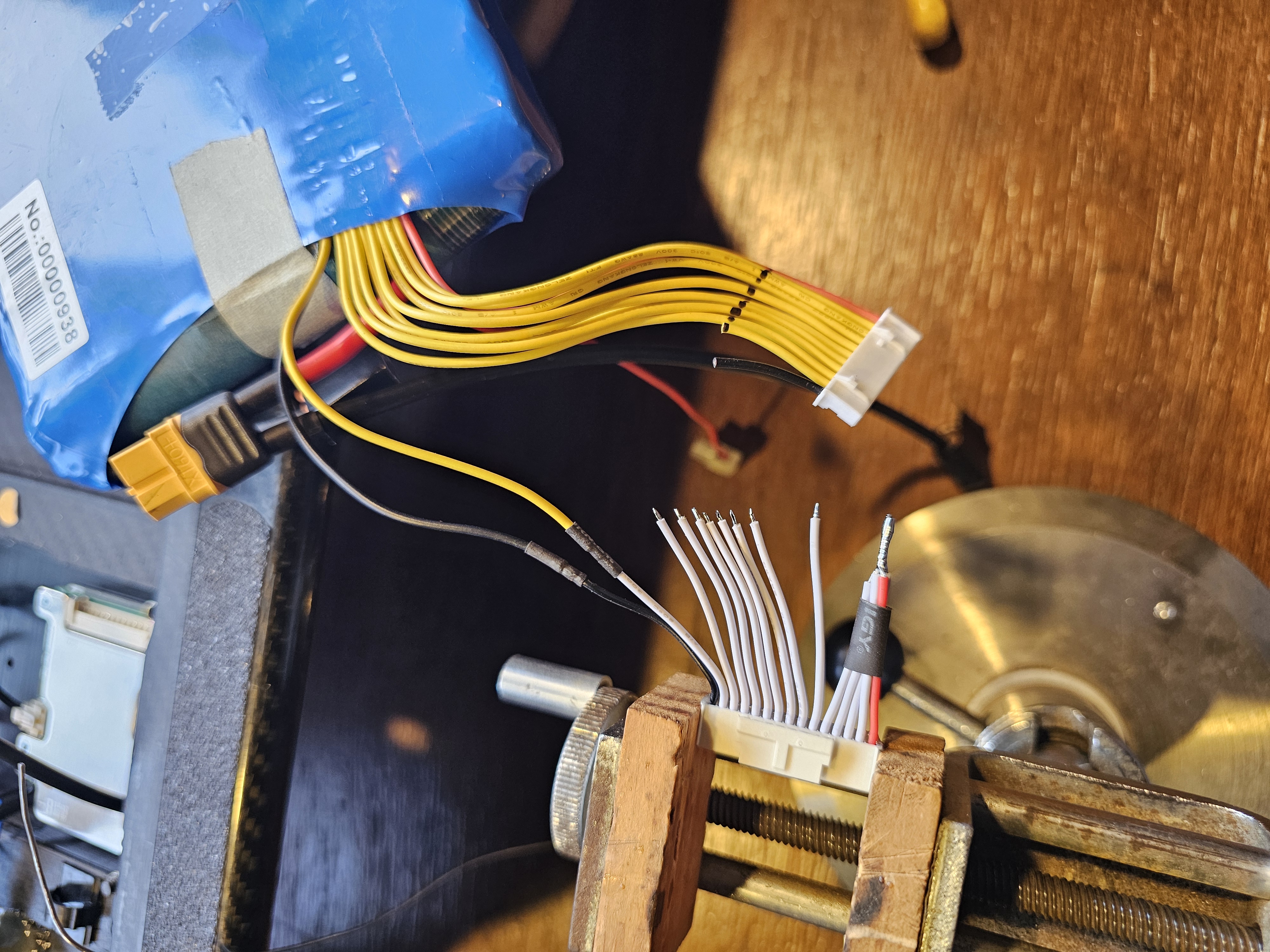
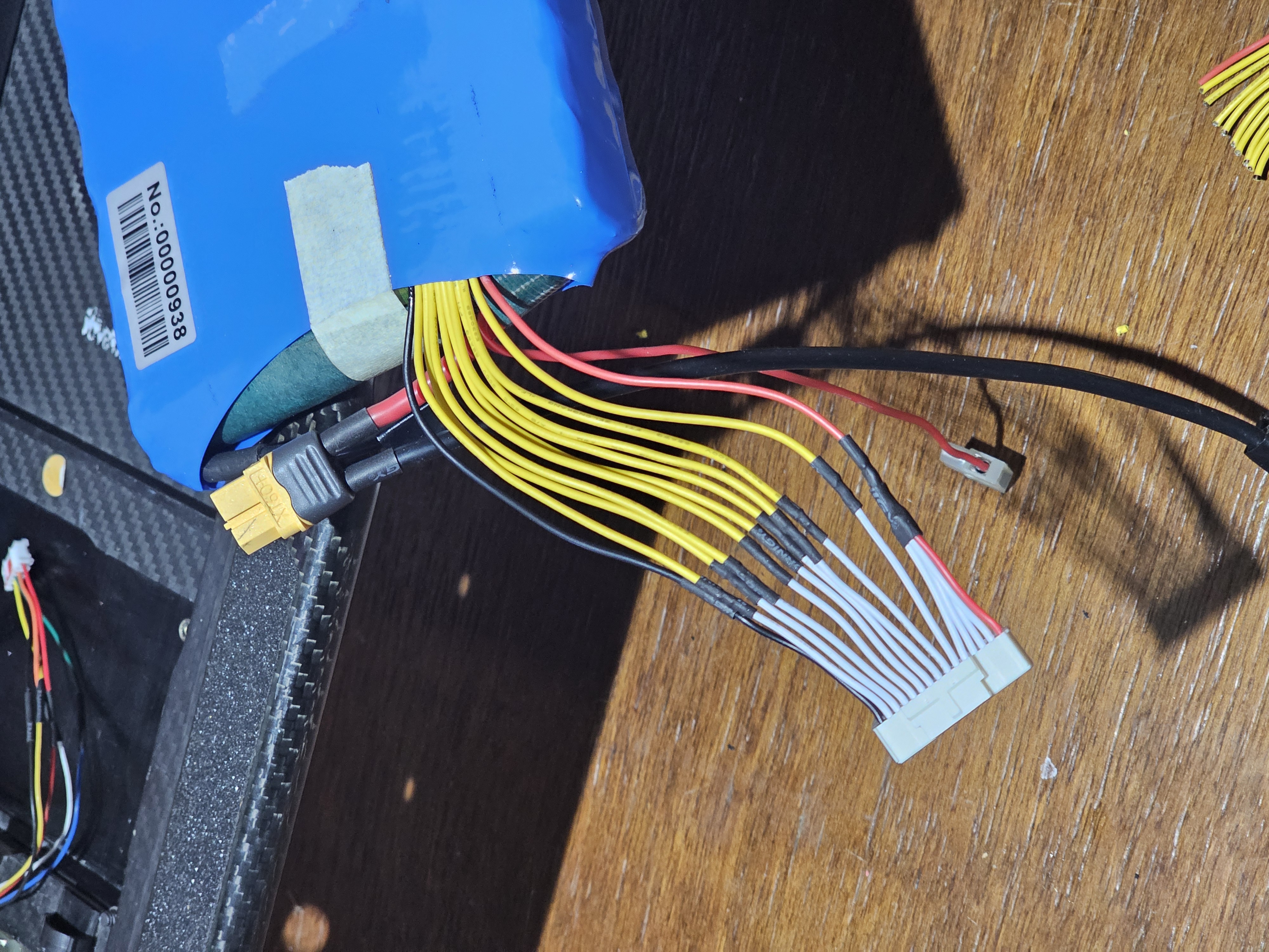
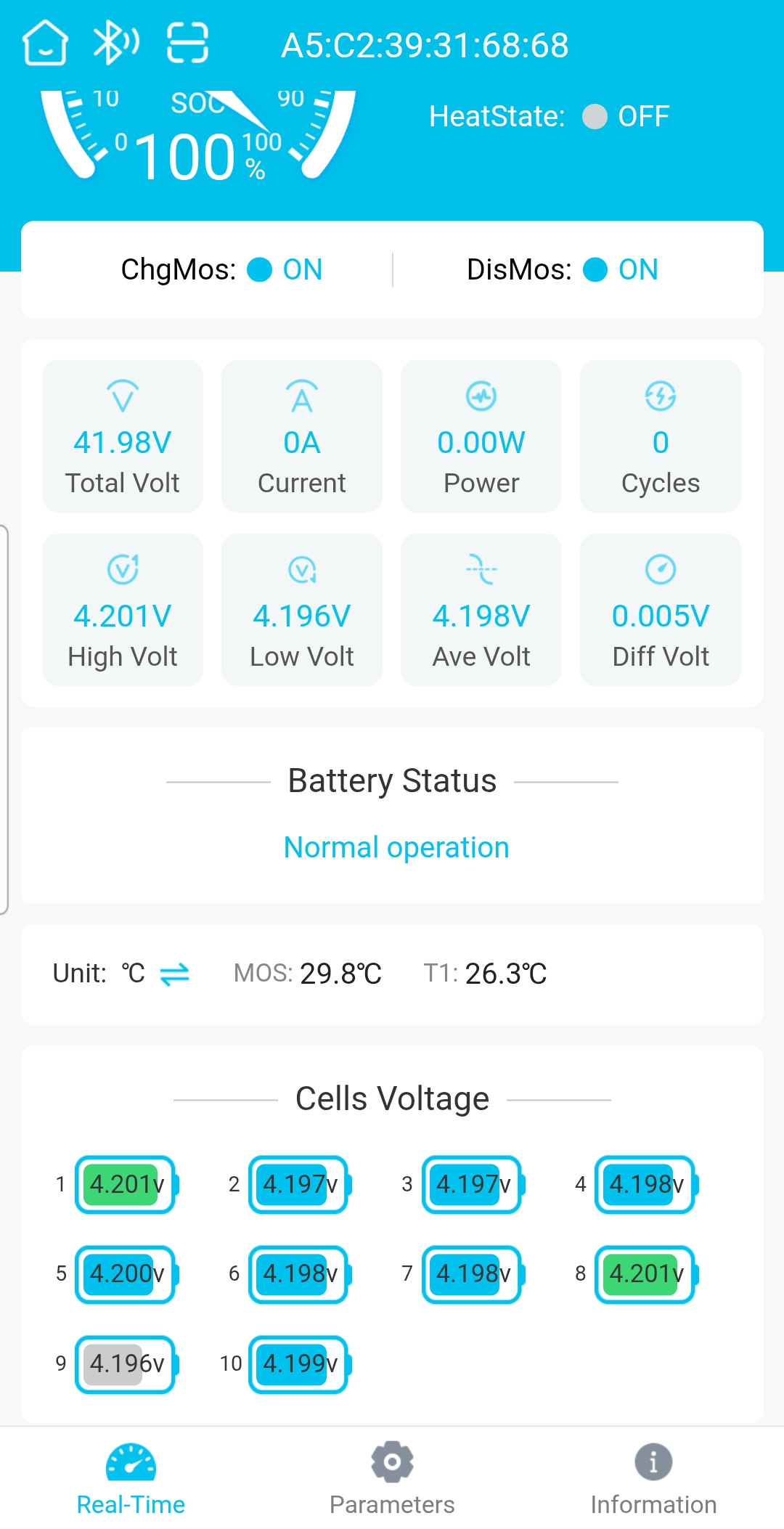
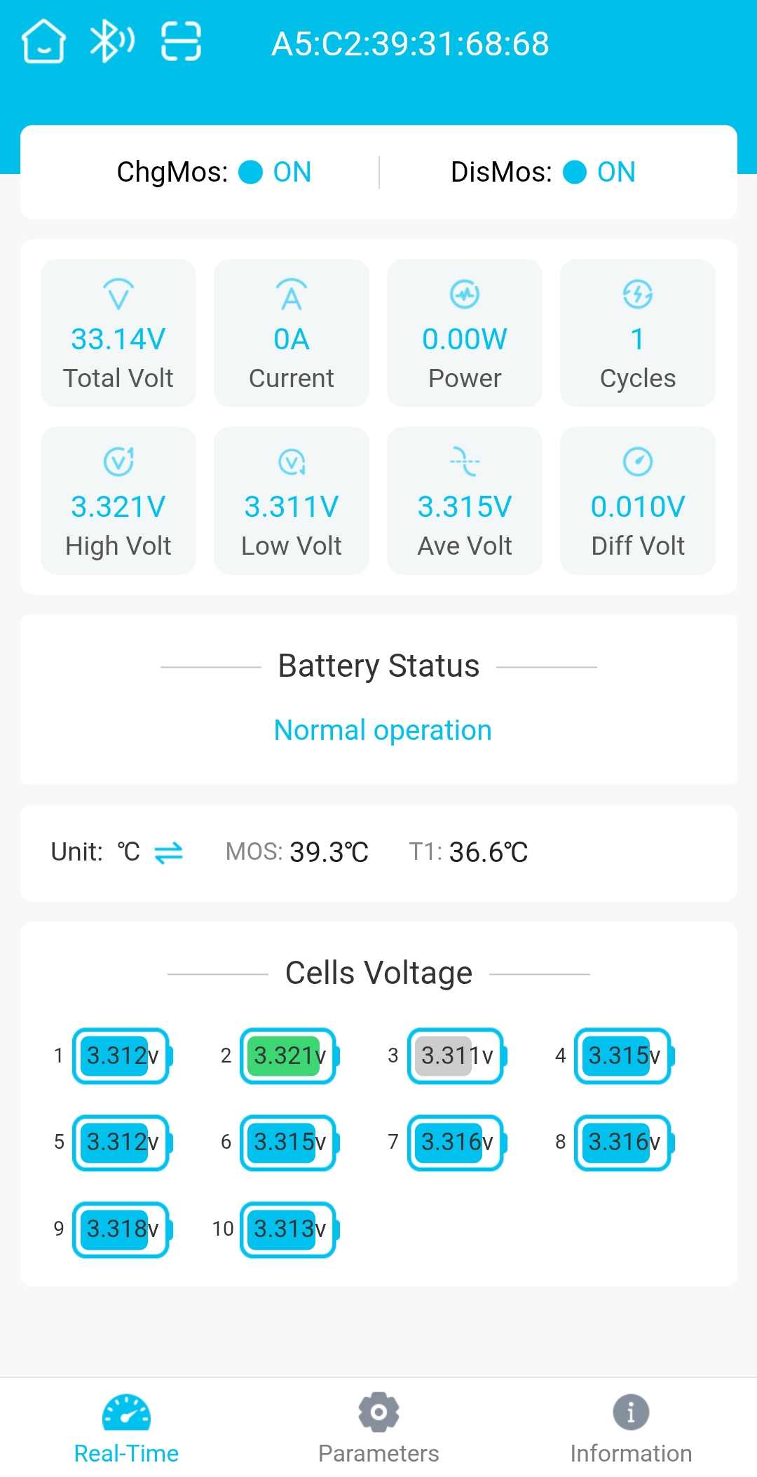
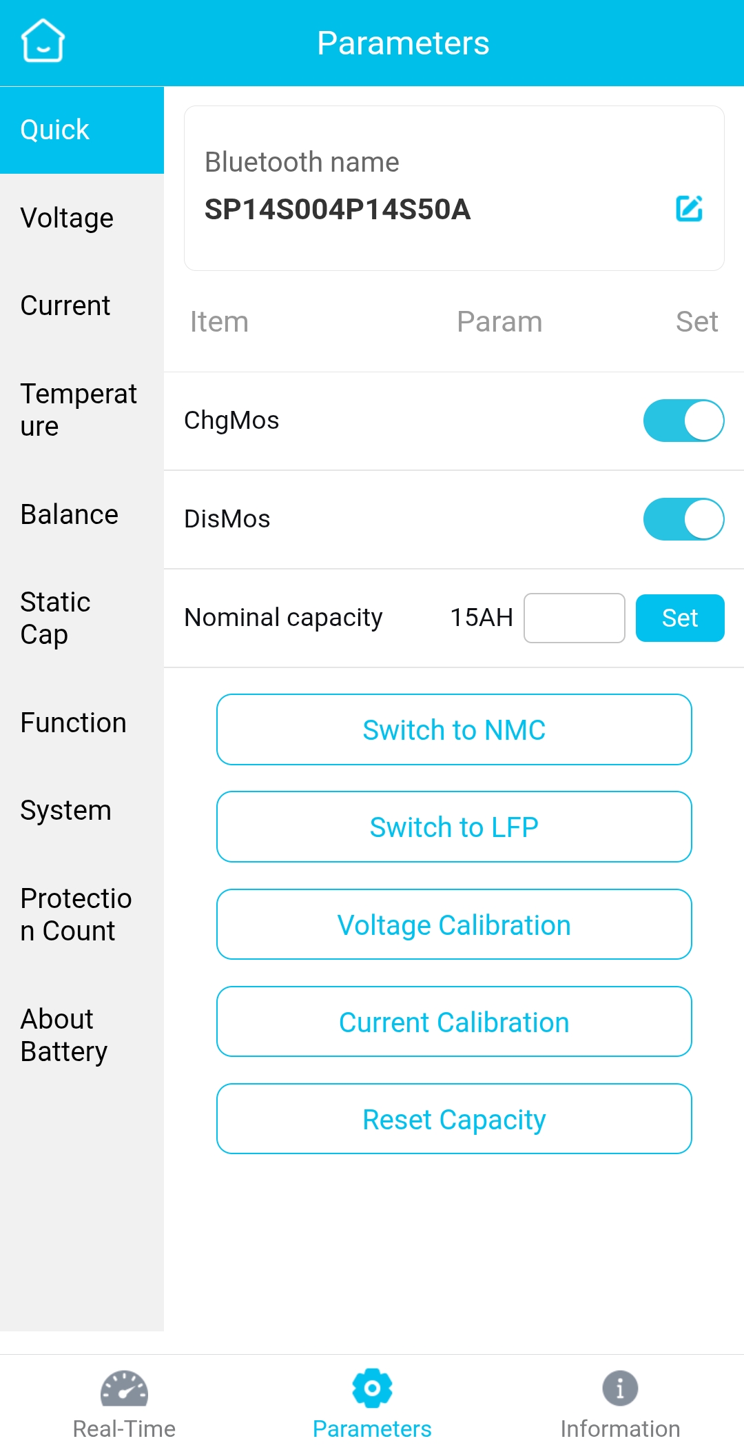
Programming was interesting (details in the next section)… Connect the negative lead to the battery first, (labelled B-) then plug in the Balance Lead (as per instructions). The BMS fires up straight away, the Bluetooth LED flashing blue deep inside between the heat sinks. Download the app and connect to it (you do need to create an account first and log in to the app). Perfect! Then it shut down after about 30 seconds. This happened 3 or 4 times until I realised it was still showing 14 cells (states auto detecting..) and until I was able to program it to 10 cells, it kept shutting down thinking 4 cells were flat and it was ‘saving’ them! Once that was done I was able to set the voltages and max currents (I set 50amp continuous), set to turn on with load, turn on Charge and Discharge, set power switch to disabled. That’s pretty much it. It does allow you to log in and check the battery easily too. This is fully charged for today’s first real test ride, then after the ride with around 5% battery remaining (yes, I went for a long ride!!)
Time to see if it works! Temporary assemble to get all wiring sorted, fire it up and program initial settings, then once happy, disassemble, clean it all out, silicone to the edges of the Evolve heatsink for waterproof, countersink the original mounting holes inside and outside then fill with silicone, add two layers of masking tape to the carbon fibre edges after sanding them round and smooth to remove any chance of cutting wiring, add some to the edge of the BMS Heatsink where the motor wires were very close to it (replaced with fibre tape later), then some thermal heat transfer double sided tape (had to use two layers to reach with the step I had left to seal the heatsink in place), another lot to the BMS and stick both in then connect all wires up, add in the receiver (antenna taped to top of battery), add the Bluetooth programmer plugged into COM 2 (antenna wire for it runs under the motor wiring as its not that critical), then align all plugs and wiring to fit neatly and used some tape to hold in place. In hindsight another 5mm on the spacer to drop everything a little lower would have been perfect.
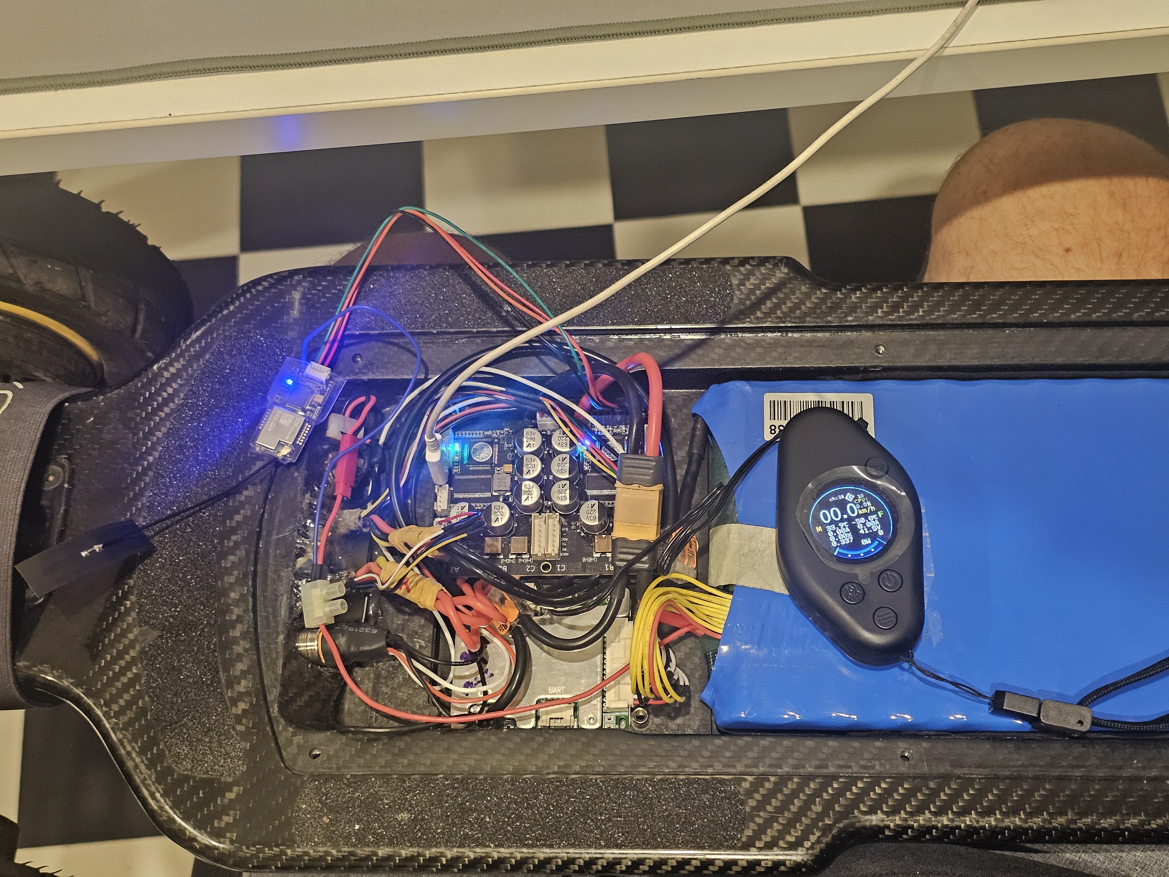
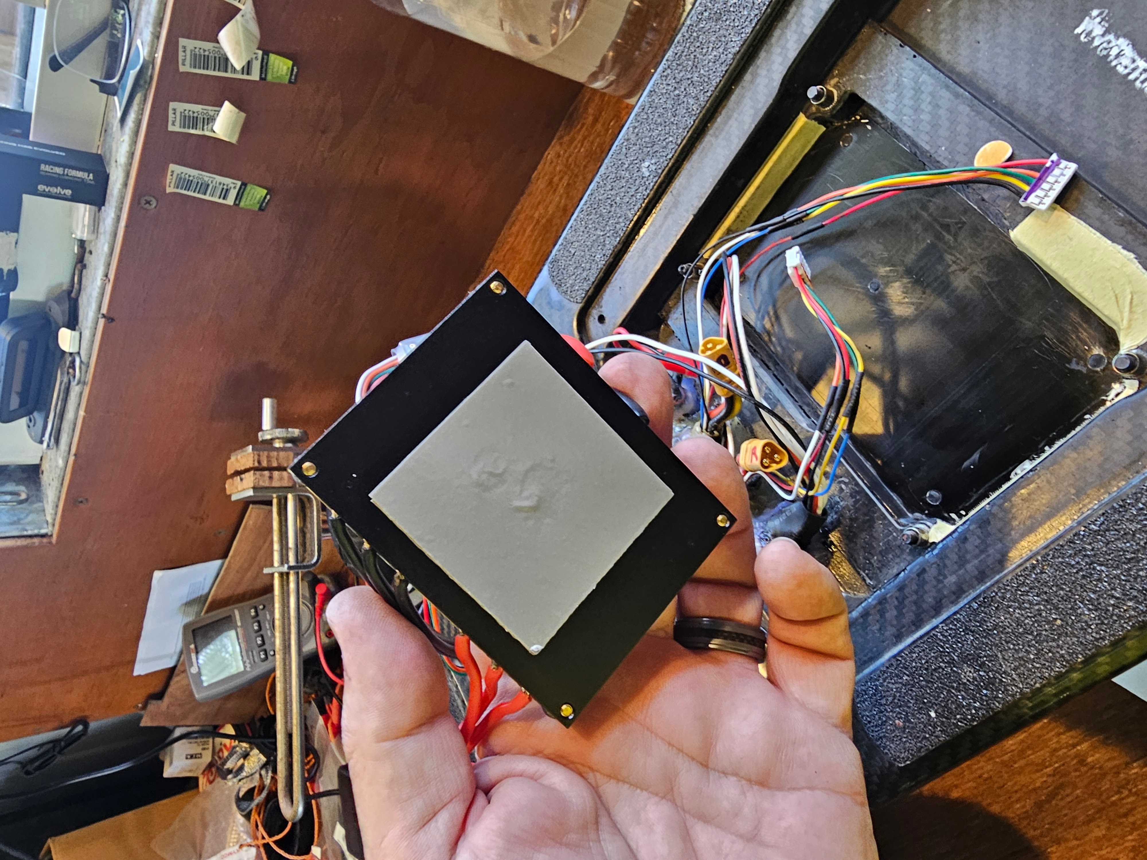
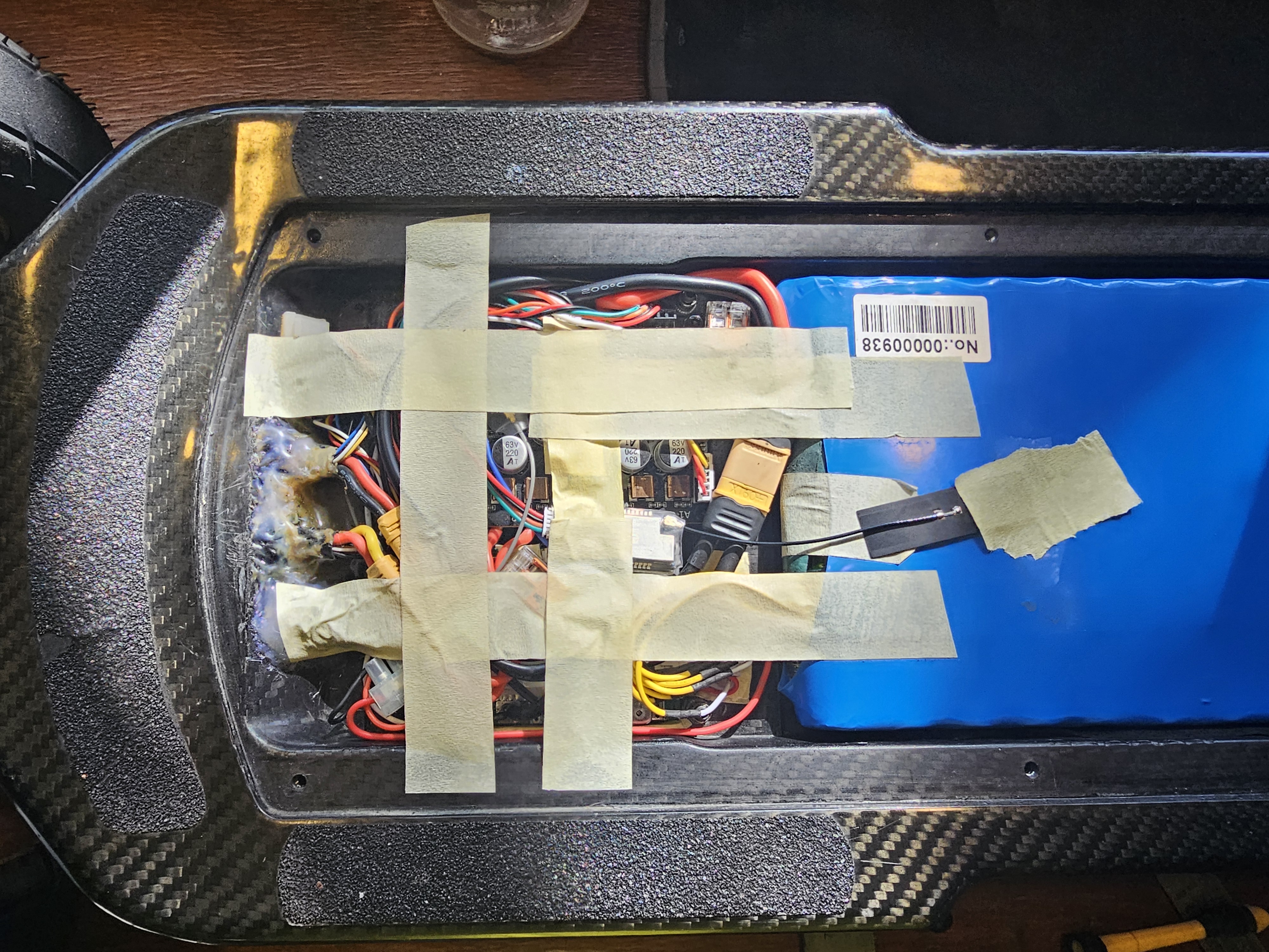
Went for a test ride a few laps around the block (ended up doing 15km) then came back and did some more research and reprogramming, then out for a 28.5km test ride this morning (normal average was 23km, max ever was 26). The Evolve had Eco, Sport and GT modes, this has L, M and H modes. I started in M and that behaved like Evolves GT mode, sending me up hills I would normally struggle to reach 20kmh, at the max 35kmh by the time I was halfway. Despite that it also somehow managed to send me 15% further than previously. I believe the previous ESC was set with different low battery limits as the original had different batteries and would sag a lot more under load. Very happy.
PROGRAMMING…
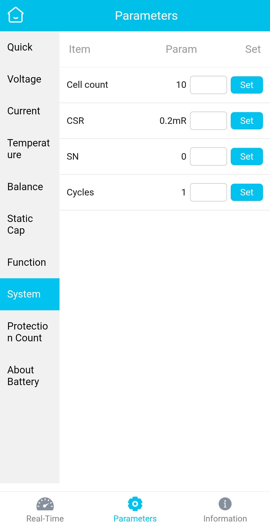
Starting with the JBD BMS. Before being able to open the app and connect you will need to create an account and verify your email address. Once that’s done, connect the Negative Battery lead (B-) and then plug in the Balance lead to turn on the BMS first time. Then log in to the app, search for the Bluetooth and connect, then I kept getting kicked out. It states it will auto detects the number of cells, but the home screen was showing cells 11 to 14 as a few millivolts each, so the BMS kept shutting down I am thinking due to low voltage cells. So when you are in, click the middle icon on the bottom (‘settings ‘Properties’ gear), select System from the left menu and set cell count to what you have – for me that was 10. Then I had no issues. So now to the top and work through the menus, not a lot to change.
Quick: set ChgMos to On, DisMos to On, Nominal Capacity to whatever you battery is – 15AH for mine.
Voltage: Default has low cell voltage at 3.3v. My cells are rated as down to 2.5v. I set them as protect at 2.6v low voltage at longer than 5 seconds. High voltage I left at the default 4.25
Current: I set mine for 70 amps, so more than that for more than 10 seconds will cut power, the rest I left mine at defaults, but read through to make sure nothing odd. In testing I am pulling max around 60 amps from the battery for a few seconds. I might even up that a little just in case, but still with over 10 seconds set I sjhouldnt have any problems.
Temperature: left mine at defaults
Balance: First turn it on, voltages I left at default (start at 3.9, 15mv accuracy) then I set mine to Static Equilibrium, the default is Charge, but Static will keep balancing even when not charging
Static Cap(acity): I left at default
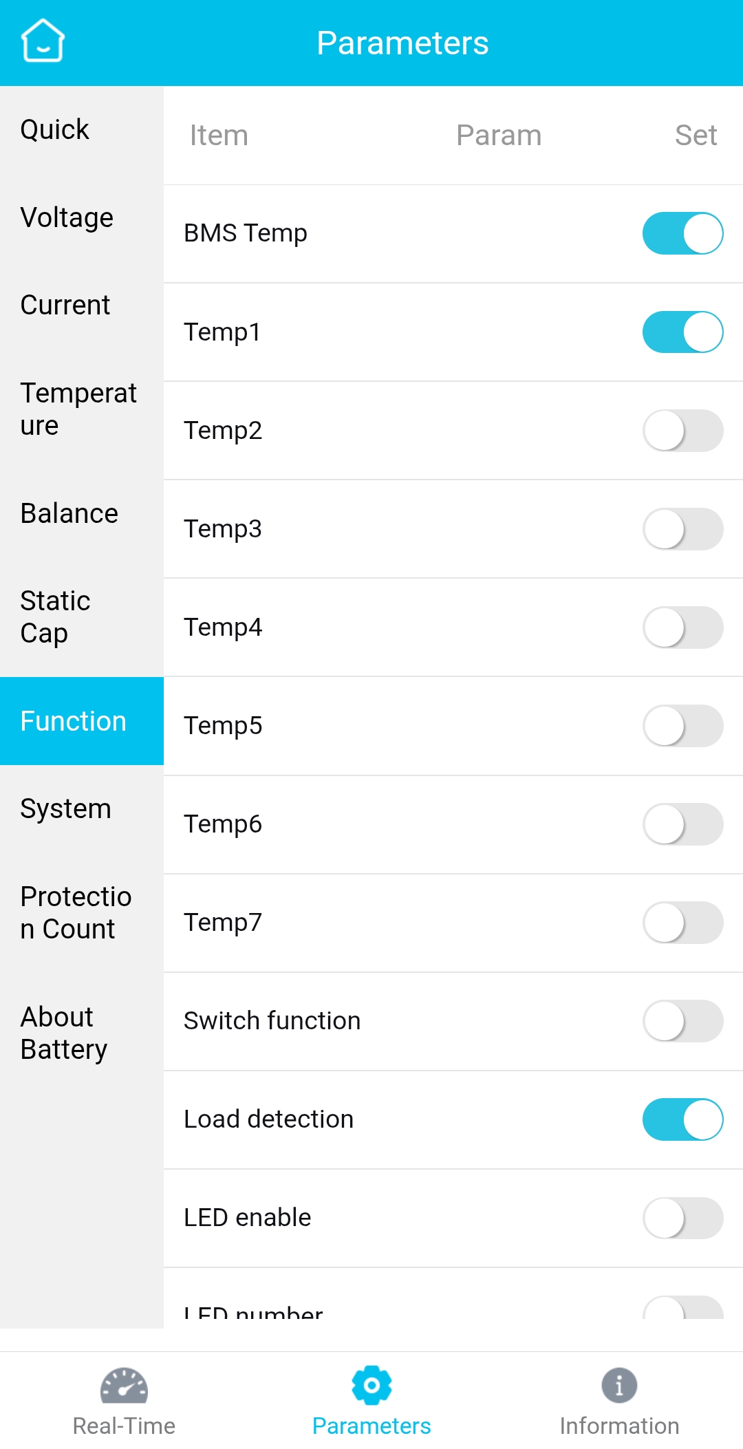
Function: BMS Temp on (that’s the MOSFETs), Temp 1 – that’s the battery temp lead, Load Detection – ON. That ones important as turning on the ESC will auto turn on the BMS if it has shut off (mine seems to stay on all the time)
System: We already set the Cell Count, you can alter the Cycles to existing levels if you want (number of battery cycles)
Protection Count: This is just telling you how many warnings have been tripped
About : just info.
FlipSky FSESC 4.20 Plus
Now the fun starts! Disclaimer – this is the first time I have programmed one of these ESCs, so please ensure the compatibility with your setup. I will add my settings I used with the relevant timer stamp from the videos, but these videos from MBoards were exactly what I needed to get my setup sorted. Not identical, but close enough and explained well enough to get me where I needed to be.
Initial setup and connections. The tips I was given was to unplug the receiver and Bluetooth programming interface from the UART and Comms ports respectively, ensure power switch is plugged in (this is the AntiSpark system), connect battery, then hit the power switch and fire it up for the first time. Check the lights are flashing on the ESC, fire up the VESC program and connect the USB cable, then click Autoconnect.
IGNORE ANY FIRMWARE UPDATE NAGS!!! There is an option in ‘Edit/Preferences’ to disable the ‘Show Firmware Update Message’ – do that, don’t update…. Most Manufacturers state to leave at the version they ship with. The FSESC4.20 Plus I received shipped with ver 5.2 – you can search and download VESC version 5.2, but they now work backward compatible very well – except for the default update nag!
First video is Motor settings – Highlights from the video with the time stamp then my comments:
- 7:02 Select Setup Motors FOC – Load Default Parameters – No.
- 7:19 Select E-Skate – next
- 7:25 Select Medium Outrunner (~750gm), discard warning
- 8:05 Fill in Battery type (Li-ion), cell numbers (mine is 10), Battery Capacity (mine was 15ah – they explain how to work this out)
- 9:20 Motor Pulley size (mine was 15t), Wheel Pulley size (mine is 66t), Wheel size (Mine is 175mm), Motor poles (default 14 for most)
- 10:05 MAKE SURE WHEELS ARE FREE TO SPIN (suspended above ground) – hit ‘run detection’ button, ensure Detect all motors over CAN Bus is selected, hit OK – motors will make noises and spin back and forth collecting data
- 11:15 Detection Results – Ensure Hall sensors detected, Motor Amperage similar for both (mine were around 35amps), click OK
- 12:10 Test motor direction and invert if needed
- 13:00 Explanation now of dual ESCs and from now on you need to make the changes manually to both ESC’s (selected in the CAV-Devices lower left of app).
- There are TWO ESC’s in the ESC box, one for each motor. Up until now the Wizard has changed all settings for both together. For EVERY change below from now on, hit the ↓M key on the right side to write to that ESC, then on the lower left of screen use the CAN-Devices section to select the other ESC, make the same changes, then hit the ↓M key again.
- Motor Settings / General menu, Current tab:
- 13:35 Motor max current. this is pulsed not direct from battery so will be much higher than the current coming from the battery – mine detected at 33.5amps, I increased to 45amps and brake at 35amps (real testing shows it peaking at 36amps for both motors, so only 18amps each motor).
- 13:58 Battery Current: Set max of Battery, BMS or Controller, which ever is lower. My Batt will run at 150amp, BMS is 50amp continuous or 150amp peak (70amps to 10 seconds), ESC is 100amps continuous. This setting is PER MOTOR, so divide the max by 2. I set them at 25amps each as my BMS continuous limit is 50amp total – I could go higher as it will allow by default up to 70 amps continuous for 10 seconds. However a test ride today though showed it maxed at only 26amps battery load total on full throttle at half speed accelerating up a hill, that’s only 13amps per motor.
- 16:18 Battery Regen max current. Per motor again, so divide max charge rate by 2. My cells are recommended 1C charge, they are 3000mah cells, so 3amp max charge rate. I have a 5p pack, so that’s 5×3 for 15amps max. Divide by 2 as per motor – I set for 7.5amps
- Motor Settings / General menu, Voltage tab:
- 18:15 Battery Voltage Cutoff. The video gives a good explanation. My cells are rated at 2.5 cutoff, I am really conservative with Lithium cells so I set mine for start cutoff at 3.2, cutoff at 3.0v. For 10 cells that’s easy – 32 and 30v. Work yours out.
- Motor Settings / General menu, RPM & Wattage Tabs:
- I left both tabs at default
- Motor Settings / General menu, Temperature tab:
- 20:35 Temperatures – I left at default
- Motor Settings / General menu, BMS and Advanced tab:
- BMS is not linked normally, so ignore, Advanced you can leave at default, the Maximum Duty Cycle is fine at 95%, DO NOT set to 100% as this will cause issues.
Notes for App Settings:
- App Settings / General – General tab:
- 1:18 Set App to use to UART (that’s for my build, using the UART connection for the VX4 Remote)
- 1:50 Shut Down Mode – They have different settings, we have a physical switch so I am not sure how this affects us, I set mine for Off_After_30M – this will shut it down after 30 min of no activity. I set BOTH ESC’s the same.
- Leave the rest at default
- press the ↓A to save for this ESC, then select the other ESC in the CAN Devices and repeat the above settings then ↓A to save to this one.
- App Settings / VESC Remote / General Tab
- 2:50 Control Type – Current No Reverse
- Ramping times I left at default
- Input Dead band – mine was at 10%, I reduced to 5% as in the video
- 3:05 Use Smart Reverse – changed to True. Brakes work as normal, but when at a full stop and hit full brakes it starts to reverse. Very handy
- Smart Reverse Max Duty cycle. Mine defaulted to 7% which was equivalent to 2kmh. OK for hill holding, but not useful for reversing. I increased to 25% as per the video default.
- press the ↓A to save for this ESC, then select the other ESC in the CAN Devices and repeat the above settings then ↓A to save to this one
- Click the Disconnect button (second down on top right), then disconnect the USB cable. Done!
Profiles:
Not usually required, however you can set maximum speed and power settings in here if you need to restrict your system, such as for the new Queensland (Australia) E-Bike and PMD (Personal Mobilitity Device – includes E-Scooter, E-Skateboard, One Wheels etc). Here I have a standard untouched profile and I have set up a 25kmh max profile which seems to work perfectly regardless of battery level.
Remote Settings:
FlipSky sent me a copy of the user manual for the VX4 Pro – not to be found on their website! Lots more info, though still lacking a lot of stuff that I keep asking them questions about. Though they do answer so happy with that. You can peruse the manual here, or below is a link to download it. Note this is the Pro version, it has 2 more buttons on the face.
Some points I have found:
- Default Screen shows battery current on the left and Motor AC Phase current on the right – both from ONLY ESC 1. So double these for total current use. Same for the Power reading, this is only for one ESC, not both (finally had this confirmed from FlipSky after being told it was both by FlipSky). So make sure to double the readings if you looking for total Battery draw.
- Odometer on the home screen is only a trip meter. The non-resetting odometer is found in the menu, however if you press enter when looking at the non-resetting one, it resets without asking for confirmation.
- Cruise Control states its speed and not current controlling, my tests say otherwise. It might be if using a different ESC such as the FlipSky FTESC (non-VESC based) – that has now been confirmed by FlipSky, only Current Control on the FSESC, not ERPM or speed. Odd, because the Speed limit in Profiles works on actual speed irrespective of current or ERPM. So setting the Cruise Control will hold the current supplied constant, meaning speed cn vary from almost stopped to full speed.
And of course an excellent video from Mboards again!
In the Menu, for me I used:
- In control Type, Select UART,
- In ESC type, select FSESC
- In Battery Cells set as per your battery (10 for me)
- Pole Pairs, default is 7 – leave unless your motors are non-standard
- Speed option km/h or mph
- Wheel type, Pulleyed for mine
- Wheel diameter, mines using 7in pneumatics – 175mm
- Motor Pulley – count the teeth, mines 15
- Wheel Pulley, count again, mines 66
- Throttle Sensitivity – I have tried all from 0 to 3 and can’t tell the difference! Supposedly 3 is more sensitive than 0
- Joystick Dead band – I changed to 5% as per video (mine was 10%)
- Low Battery Warning – on – gives a vibration when board or controller battery gets below 10%
- Theme Colour – tried all three, blue looked great but red was easiest to see battery level in the sun
- Default Speed Gear – M is my choice – this doesn’t affect top speed but does effect max current and therefore acceleration. I find M is similar to GT mode on the Evolve remote, H is insane compared to original! L is slow accelerating and slow up hills.
- Cruise Switch – mines on, but its horrid to use as it is constant current not constant speed. Confirmed with FlipSky, only works as current control on VESC (works as ERPM control on FTESC)
- Reverse Switch – off for me, so you cant change from F to R, if you do then you have full speed in reverse (if you want it, you need to change the Control Type in App settings in the previous video to Current instead of Current No Reverse).
- Gear Lock – off, so you can change from L to M to H
- Total Distance – non auto resetting odometer. If you hold down the menu button it will reset to 0 and if you do this accidentally you CANNOT undo it!
I also was a bit nervous about the display, so as I wanted to replace the screen protector on my phone (plastic as its a Samsung with curved screen), I stuck the old protector to the backing plastic of the new protector, traced a circle the right size for the screen and cut out a protector for it. Much happier! I am also looking to get a plastic 3D cover printed up for it too, I just don’t have a 3D printer yet (its coming)..
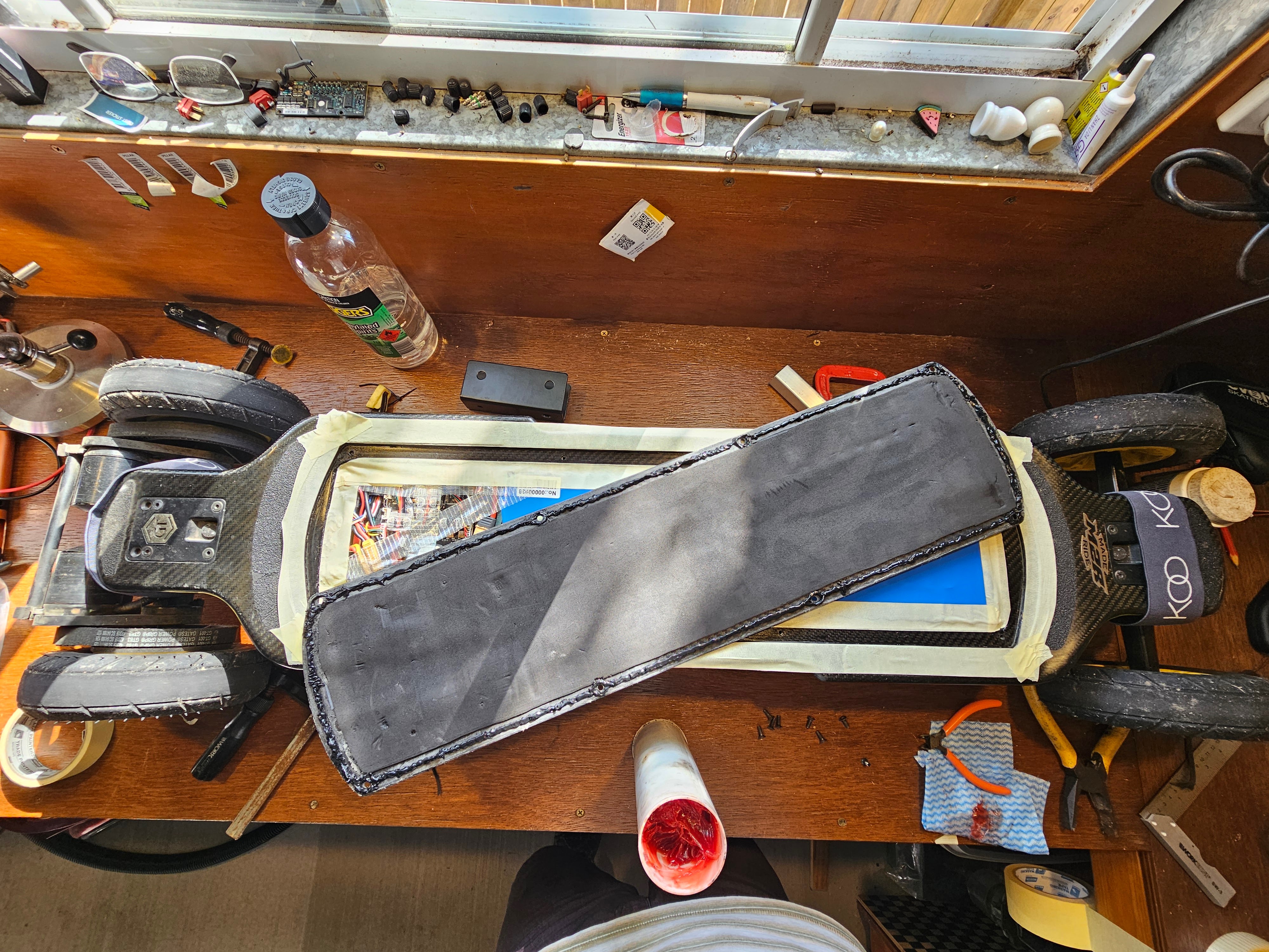
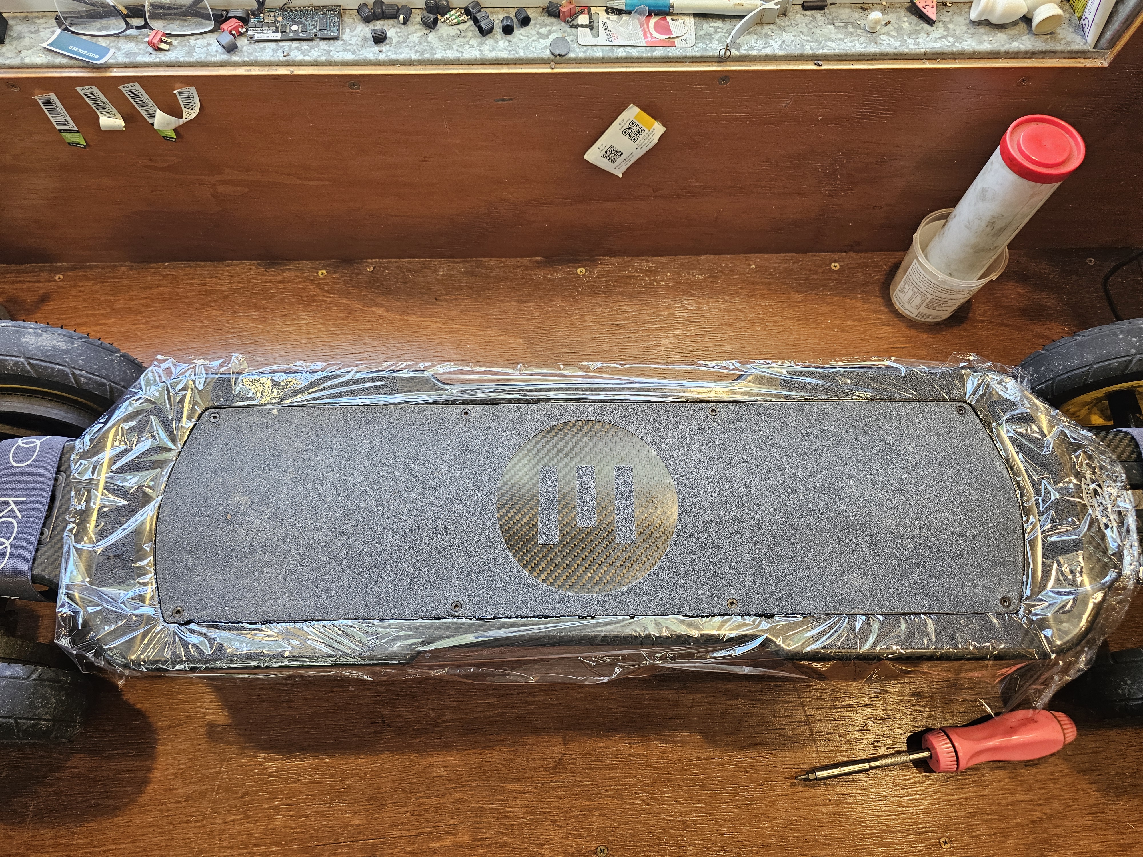
Now I have the cabling into the board all sealed from water, I decided to do the same to the deck. Cleaned off 10mm all the way around the lid of the original foam that didn’t stop water, cleaned the lip on the deck, smeared silicone all around the edge of the lid, circling the screw holes to keep water from coming through them too, (took two goes – not enough silicone applied the first time!), The first time I greased up the deck with Lithium grease to stop the silicone from sticking, sort of worked.. The second time I decided to lay a sheet of glad wrap over the deck then drop the lid in place. Once in place, some grease on the screws and screw the lid down to level with the deck and let set. I might even go one more run and lift/level the deck a tiny bit more and add more silicon to one side where i was a bit skimpy.
Some things noted or not resolved as yet.
- Cruise Control is pretty useless on the VESC boards, as it still only uses current control, so if you set it at say 20kmh on level ground, its OK, then a slight downhill it hits max speed (35kmh for me) then a slight up hill and it drops to 5kmh, a steep hill it stopped… Useless.
- Display on the left shows Battery Current, the right shows Motor Current. FlipSky confirmed it shows total current for both motors when using the Dual Mini FSESC4.20, however testing shows that’s probably not right, setting braking at max -7.5amps battery per ESC and the display shows -7.5amps at full brakes.
- UPDATE. After lots of back and forth with FlipSky they now confirm they were wrong and the display is just for one of the ESC, not both combined (the one on the same side as the UART port – motor wiring labelled A1, B1, C1. The other side is labelled A2, B2 & C2 and is NOT included in the display readings.
Feel free to drop a note below or share on Socials
Recent Comments